|
当您的IoT项目由电源适配器供电时,您不会太关心功耗。但是,如果您要使用电池为项目供电,则需要计算每个MA电流。
ESP32可能是相对功耗较高的设备,具体取决于其处于哪种状态。通常,在通过WiFi传输数据时240mA左右,它的正常操作时约75mA。
这里的解决方案是通过利用深度睡眠模式来降低ESP32的功耗。
ESP32深度睡眠 在深度睡眠模式下,CPU、大多数RAM和所有数字外围设备都可以关闭。芯片唯一保持运行的部分是: ● ULP协处理器 ● RTC控制器 ● RTC外围设备 ● RTC内存
芯片将消耗约0.15 mA(如果ULP协处理器打开)至10µA。

在深度睡眠模式下,主CPU被关闭,而ULP协处理器可以采用传感器读数,并在必要时唤醒CPU。这种睡眠模式称为ULP传感器监控模式。这对于设计应用程序需要由外部事件或计时器或两者组合唤醒的应用程序很有用,同时保持最少的功耗。
与CPU一起,芯片的主要内存也被禁用。因此,存储在该内存中的所有内容都被删除且无法访问。
由于RTC存储持续供电,因此即使在深度睡眠期间也保留了其内容,并且可以在芯片唤醒后检索。这就是为什么芯片在进入深度睡眠之前将Wi-Fi和蓝牙连接数据存储在RTC内存中的原因。
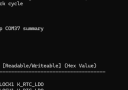
如果要在重新启动后使用数据,请通过使用RTC_DATA_ATTR属性来定义全局变量,将其存储在RTC内存中。例如,RTC_DATA_ATTR int myVar = 0。
从深度睡眠中出来后,芯片通过复位重新启动,并从一开始就开始执行程序。
与其他睡眠模式不同,系统无法自动进入深度睡眠模式。 esp_deep_sleep_start()函数用于配置唤醒源后立即进入深度睡眠。
ESP32深度睡眠唤醒源 ESP32可以使用多个源从深度睡眠模式唤醒。这些源是: ● 定时器 ● 触摸引脚 ● 外部唤醒(Ext0&Ext1) 可以组合多个唤醒源,当触发其中一个源时,芯片将被唤醒。
ESP32唤醒源:定时器 ESP32 RTC控制器具有一个内置定时器,您可以在预定义的时间后用来唤醒ESP32。
此功能在需要时间戳或日常任务的同时保持低功耗的项目中特别有用。
esp_sleep_enable_timer_wakeup(time_in_us)函数用于将计时器配置为唤醒源。
示例代码 让我们使用库中的示例来看看它的工作原理。打开您的Arduino IDE,然后导航到File > Examples > ESP32 > Deep Sleep,然后打开TimerWakeup草图。
该草图演示了最基本的深度睡眠示例,其中定时器是唤醒源,以及如何将数据存储在RTC内存中以在复位后使用它。 - #define uS_TO_S_FACTOR 1000000ULL /* Conversion factor for micro seconds to seconds */
- #define TIME_TO_SLEEP 5 /* Time ESP32 will go to sleep (in seconds) */
- RTC_DATA_ATTR int bootCount = 0;
- /*
- Method to print the reason by which ESP32
- has been awaken from sleep
- */
- void print_wakeup_reason(){
- esp_sleep_wakeup_cause_t wakeup_reason;
- wakeup_reason = esp_sleep_get_wakeup_cause();
- switch(wakeup_reason)
- {
- case ESP_SLEEP_WAKEUP_EXT0 : Serial.println("Wakeup caused by external signal using RTC_IO"); break;
- case ESP_SLEEP_WAKEUP_EXT1 : Serial.println("Wakeup caused by external signal using RTC_CNTL"); break;
- case ESP_SLEEP_WAKEUP_TIMER : Serial.println("Wakeup caused by timer"); break;
- case ESP_SLEEP_WAKEUP_TOUCHPAD : Serial.println("Wakeup caused by touchpad"); break;
- case ESP_SLEEP_WAKEUP_ULP : Serial.println("Wakeup caused by ULP program"); break;
- default : Serial.printf("Wakeup was not caused by deep sleep: %d\n",wakeup_reason); break;
- }
- }
- void setup(){
- Serial.begin(115200);
- delay(1000); //Take some time to open up the Serial Monitor
- //Increment boot number and print it every reboot
- ++bootCount;
- Serial.println("Boot number: " + String(bootCount));
- //Print the wakeup reason for ESP32
- print_wakeup_reason();
- /*
- First we configure the wake up source
- We set our ESP32 to wake up every 5 seconds
- */
- esp_sleep_enable_timer_wakeup(TIME_TO_SLEEP * uS_TO_S_FACTOR);
- Serial.println("Setup ESP32 to sleep for every " + String(TIME_TO_SLEEP) +
- " Seconds");
- /*
- Next we decide what all peripherals to shut down/keep on
- By default, ESP32 will automatically power down the peripherals
- not needed by the wakeup source, but if you want to be a poweruser
- this is for you. Read in detail at the API docs
- http://esp-idf.readthedocs.io/en/latest/api-reference/system/deep_sleep.html
- Left the line commented as an example of how to configure peripherals.
- The line below turns off all RTC peripherals in deep sleep.
- */
- //esp_deep_sleep_pd_config(ESP_PD_DOMAIN_RTC_PERIPH, ESP_PD_OPTION_OFF);
- //Serial.println("Configured all RTC Peripherals to be powered down in sleep");
- /*
- Now that we have setup a wake cause and if needed setup the
- peripherals state in deep sleep, we can now start going to
- deep sleep.
- In the case that no wake up sources were provided but deep
- sleep was started, it will sleep forever unless hardware
- reset occurs.
- */
- Serial.println("Going to sleep now");
- Serial.flush();
- esp_deep_sleep_start();
- Serial.println("This will never be printed");
- }
- void loop(){
- //This is not going to be called
- }
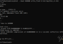
上传草图后,打开串口显示器,将波特率设置为115200 bps。
ESP32每5秒醒来一次,打印出唤醒原因并在串口显示器上启动,然后再次入睡。

现在,按下EN按钮复位ESP32,它应该再次将启动器重置为1,以表明RTC内存已完全擦除。
代码说明 前两行代码定义了ESP32入睡的时间。
此示例使用从微秒到秒的转换系数,因此您可以在time_to_sleep变量中以秒为单位设置睡眠时间。在这里,ESP32进入深度睡眠模式5秒钟。 - #define uS_TO_S_FACTOR 1000000ULL /* Conversion factor for micro seconds to seconds */
- #define TIME_TO_SLEEP 5 /* Time ESP32 will go to sleep (in seconds) */
如前所述,您可以将数据保存在ESP32的RTC内存(8KB SRAM)中,该内存在深度睡眠期间未删除。但是,当ESP32复位时,它将被删除。
要将数据保存在RTC内存上,您只需要在定义变量之前添加RTC_DATA_ATTR 属性即可。在此示例中,bootCount变量保存在RTC内存中。它将计算ESP32从深度睡眠中醒来的次数。 - RTC_DATA_ATTR int bootCount = 0;
接下来,定义了print_wakeup_reason()函数,该函数打印出ESP32从深度睡眠中唤醒的原因。 - void print_wakeup_reason(){
- esp_sleep_wakeup_cause_t wakeup_reason;
- wakeup_reason = esp_sleep_get_wakeup_cause();
- switch(wakeup_reason)
- {
- case ESP_SLEEP_WAKEUP_EXT0 : Serial.println("Wakeup caused by external signal using RTC_IO"); break;
- case ESP_SLEEP_WAKEUP_EXT1 : Serial.println("Wakeup caused by external signal using RTC_CNTL"); break;
- case ESP_SLEEP_WAKEUP_TIMER : Serial.println("Wakeup caused by timer"); break;
- case ESP_SLEEP_WAKEUP_TOUCHPAD : Serial.println("Wakeup caused by touchpad"); break;
- case ESP_SLEEP_WAKEUP_ULP : Serial.println("Wakeup caused by ULP program"); break;
- default : Serial.printf("Wakeup was not caused by deep sleep: %d\n",wakeup_reason); break;
- }
- }
在setup()函数中,我们首先将串口通信初始化。 然后将bootCount变量加1,然后打印到串口显示器上,以显示ESP32从深度睡眠中醒来的次数。 - ++bootCount;
- Serial.println("Boot number: " + String(bootCount));
然后调用print_wakeup_reason()函数,但是您也可以调用要执行所需任务的任何函数,例如,读取传感器的值。 接下来,我们使用esp_sleep_enable_timer_wakeup(time_in_us)函数配置定时器唤醒源。在这里,ESP32将每5秒醒来一次。 - esp_sleep_enable_timer_wakeup(TIME_TO_SLEEP * uS_TO_S_FACTOR);
最后,通过调用esp_deep_sleep_start()函数来使ESP32进入睡眠模式。 在此草图中,ESP32在setup()函数本身中进入深度睡眠,因此它永远不会达到loop()函数。因此,loop()函数是空的。 - void loop(){
- //This is not going to be called
- }
|