|
GY-521模块是一款基于MPU-6050 MEMS(微机电系统)的分线板(Breakout Board),MPU-6050具有一个3轴陀螺仪、一个3轴加速度计、数字运动处理器(DMP)和温度传感器。数字运动处理器可用于直接在电路板上处理复杂算法。通常,DMP处理将来自传感器的原始值转换为稳定位置数据的算法。本篇文章将简要介绍GY-521 / MPU-6050模块。主要介绍如何检索原始传感器值。通过使用I2C串行数据总线检索传感器值,该总线仅需要两条线(SCL和SDA)。如果您打算使用所有功能,或者需要可靠且稳定的位置数据,那么我建议您先看看现成的库。请点击此链接以找到包含许多示例的库:https://github.com/jrowberg/i2cdevlib/tree/master/Arduino/MPU6050。

所需的材料清单: – Arduino Uno开发板 – 跳线 – 面包板 – GY-521模块
引脚分布: GY-521分线板具有八个引脚: ● VCC(分线板上有一个稳压器。因此,您可以将其连接到3.3V和5V电源。) ● GND ● SCL(I2C协议的串行时钟线。) ● SDA(I2C协议的串行数据线。) ● XDA(辅助数据=> I2C主串行数据,用于将模块连接到外部传感器。) ● XCL(辅助时钟=> I2C主串行时钟,用于将模块连接到外部传感器。) ● AD0(如果此引脚为LOW,则该板的I2C地址将为0x68。否则,如果该引脚为HIGH,则该地址将为0x69。) ● INT(中断数字输出)
接线方式: 在本篇文章中,我们将仅使用前四个引脚:VCC、GND、SDA和SCL。首先,我们将模块的VCC连接到Arduino的5V引脚。然后,模块的GND连接到Arduino的其中一个GND引脚。 接下来,我们需要在模块和Arduino之间建立I2C连接。大多数Arduino Uno开发板都有SCL和SDA引脚。如果您有这样的Arduino Uno,只需将SCL连接到SCL并将SDA连接到SDA。 如果您在Arduino上找不到SCL和SDA引脚,则必须使用其他引脚。对于每种类型的Arduino,SCL和SDA都连接到不同的引脚: ● Arduino Uno、Arduino Ethernet、Arduino Nano:A4(SDA)、A5(SCL) ● Arduino Mega2560:20(SDA)、21(SCL) ● Arduino Leonardo:2(SDA)、3(SCL) ● Arduino Due:20(SDA)、21(SCL)
因此,如果您使用的是Arduino Uno开发板,则将Arduino的A4引脚连接到模块的SDA引脚。接下来,将Arduino的A5引脚连接到模块的SCL引脚。

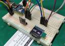
Fritzing文件显示了如何将GY-521分线板连接到Arduino Uno。
示例源代码: 我们利用Arduino平台的内置库(Wire)在Arduino Uno和GY-521传感器之间建立I2C连接。在源代码的开头,包含Wire库的头文件。接下来,我们定义并声明一些变量。 然后,定义一个转换函数。转换函数可确保以后将所有传感器值打印到串口监视器时,它们具有相同的宽度。
在setup()函数中,建立串口连接。此外,我们开始向GY-521分线板进行第一次I2C传输将其从睡眠模式唤醒。
在loop()函数中,从GY-521模块请求了七个传感器值(3x加速度计、1x温度和3x陀螺仪)。 MPU-6050有许多可以读取的寄存器。这些寄存器中的十四个包含我们需要的传感器值。第一步,我们告诉GY-521模块将从哪里开始读取(“ Wire.write(0x3B);”)。然后,请求读取14个寄存器(“ Wire.requestFrom(MPU_ADDR,7 * 2,true);”)。如果您想知道为什么读取14个寄存器而不是7个寄存器,原因很简单:每个传感器值的大小为2个字节。由于每个寄存器的大小为一个字节,因此必须通过访问两个寄存器来检索单个传感器值。第一个寄存器包含“高字节”,第二个寄存器包含“低字节”。接下来,将检索所有值并将其打印输出到串口连接。在loop()函数结束时,添加了一秒的延迟。 - #include "Wire.h" // This library allows you to communicate with I2C devices.
- const int MPU_ADDR = 0x68; // I2C address of the MPU-6050. If AD0 pin is set to HIGH, the I2C address will be 0x69.
- int16_t accelerometer_x, accelerometer_y, accelerometer_z; // variables for accelerometer raw data
- int16_t gyro_x, gyro_y, gyro_z; // variables for gyro raw data
- int16_t temperature; // variables for temperature data
- char tmp_str[7]; // temporary variable used in convert function
- char* convert_int16_to_str(int16_t i) { // converts int16 to string. Moreover, resulting strings will have the same length in the debug monitor.
- sprintf(tmp_str, "%6d", i);
- return tmp_str;
- }
- void setup() {
- Serial.begin(9600);
- Wire.begin();
- Wire.beginTransmission(MPU_ADDR); // Begins a transmission to the I2C slave (GY-521 board)
- Wire.write(0x6B); // PWR_MGMT_1 register
- Wire.write(0); // set to zero (wakes up the MPU-6050)
- Wire.endTransmission(true);
- }
- void loop() {
- Wire.beginTransmission(MPU_ADDR);
- Wire.write(0x3B); // starting with register 0x3B (ACCEL_XOUT_H) [MPU-6000 and MPU-6050 Register Map and Descriptions Revision 4.2, p.40]
- Wire.endTransmission(false); // the parameter indicates that the Arduino will send a restart. As a result, the connection is kept active.
- Wire.requestFrom(MPU_ADDR, 7*2, true); // request a total of 7*2=14 registers
-
- // "Wire.read()<<8 | Wire.read();" means two registers are read and stored in the same variable
- accelerometer_x = Wire.read()<<8 | Wire.read(); // reading registers: 0x3B (ACCEL_XOUT_H) and 0x3C (ACCEL_XOUT_L)
- accelerometer_y = Wire.read()<<8 | Wire.read(); // reading registers: 0x3D (ACCEL_YOUT_H) and 0x3E (ACCEL_YOUT_L)
- accelerometer_z = Wire.read()<<8 | Wire.read(); // reading registers: 0x3F (ACCEL_ZOUT_H) and 0x40 (ACCEL_ZOUT_L)
- temperature = Wire.read()<<8 | Wire.read(); // reading registers: 0x41 (TEMP_OUT_H) and 0x42 (TEMP_OUT_L)
- gyro_x = Wire.read()<<8 | Wire.read(); // reading registers: 0x43 (GYRO_XOUT_H) and 0x44 (GYRO_XOUT_L)
- gyro_y = Wire.read()<<8 | Wire.read(); // reading registers: 0x45 (GYRO_YOUT_H) and 0x46 (GYRO_YOUT_L)
- gyro_z = Wire.read()<<8 | Wire.read(); // reading registers: 0x47 (GYRO_ZOUT_H) and 0x48 (GYRO_ZOUT_L)
-
- // print out data
- Serial.print("aX = "); Serial.print(convert_int16_to_str(accelerometer_x));
- Serial.print(" | aY = "); Serial.print(convert_int16_to_str(accelerometer_y));
- Serial.print(" | aZ = "); Serial.print(convert_int16_to_str(accelerometer_z));
- // the following equation was taken from the documentation [MPU-6000/MPU-6050 Register Map and Description, p.30]
- Serial.print(" | tmp = "); Serial.print(temperature/340.00+36.53);
- Serial.print(" | gX = "); Serial.print(convert_int16_to_str(gyro_x));
- Serial.print(" | gY = "); Serial.print(convert_int16_to_str(gyro_y));
- Serial.print(" | gZ = "); Serial.print(convert_int16_to_str(gyro_z));
- Serial.println();
-
- // delay
- delay(1000);
- }
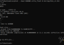
如果代码已编译并传输到Arduino Uno后,则应该在Arduino IDE的串口监视器中看到传感器值。 此外,当旋转或移动GY-521分线板时,传感器值应根据移动而变化。

如前所述,以上基本上是GY-521的“ hello world程序”。 如果您打算更认真地使用该分线板,我强烈建议您深入研究MPU-6050 MEMS。 |