|
DSLR远程触发器的Arduino代码 本文使用了两种不同的代码,一种用于发送端,另一种用于接收端。
发送端的代码: 首先包括所需的库文件。 - //Include Libraries
- #include <SPI.h>
- #include <nRF24L01.h>
- #include <RF24.h>
- #include "printf.h"
- #include <ArduinoJson.h>
在代码中设置通讯地址,发送端和接收端都必须相同。 - //address through which two modules communicate.
- const byte address[6] = {0xe1, 0xe1, 0xe1, 0xe1, 0xe1};
定义一个布尔值,其中触发状态将从“true”更改为“false”,反之亦然。 - volatile bool isTrigger = false;
接下来在运行实际应用程序之前启动NRF24L01。在这里,还需要设置RF范围、数据类型和状态。 nRF24L01设置为发射器,并且还设置为具有最大RF功率的远程距离。另外,输入先前设置的地址。 - void setup()
- {
- Serial.begin(9600);
- printf_begin();
- Serial.println(F("\n\rRF24/examples/scanner/"));
- // Setup and configure rf radio
- radio.begin();
- radio.setAutoAck(false);
- //set the address
- radio.openWritingPipe(address);
- radio.setPALevel(RF24_PA_MIN); //set as: RF24_PA_MIN, RF24_PA_LOW, RF24_PA_HIGH, RF24_PA_MAX
- radio.setDataRate(RF24_2MBPS); //set as: F24_250KBPS, F24_1MBPS, F24_2MBPS ==>250KBPS = longest range
- radio.setChannel(115); //sets channel from 2.4 to 2.524 GHz in 1 MHz increments 2.483.5 GHz is normal legal limit
- radio.setCRCLength(RF24_CRC_8);
- // radio.printDetails();
- //Set module as transmitter
- radio.stopListening();
设置发送端nRF24L01之后,该设置按钮输入,该按钮输入将在触发期间由用户按下。引脚被设置为输入模式。 - pinMode(SHUTT_REMOTE_TRIGGER_PIN, INPUT); // sets the digital pin "SHUTT_TRIGGER_PIN" as output
- // attachInterrupt(digitalPinToInterrupt(SHUTT_REMOTE_TRIGGER_PIN), shutter_remote_trigger, LOW);
- // attachInterrupt(digitalPinToInterrupt(SHUTT_REMOTE_TRIGGER_PIN), shutter_remote_trigger, HIGH );
- }
- void shutter_remote_trigger() {
- isTrigger = true;
- }
- // Variables will change:
- int ledState = HIGH; // the current state of the output pin
- int buttonState; // the current reading from the input pin
- int lastButtonState = LOW; // the previous reading from the input pin
- // the following variables are unsigned longs because the time, measured in
- // milliseconds will quickly become a bigger number than can be stored in an int.
- unsigned long lastDebounceTime = 0; // the last time the output pin was toggled
- unsigned long debounceDelay = 50; // the debounce time; increase if the output flickers
在loop()函数中,将持续监视按钮状态,并且每当按下按钮状态时,就会将JSON语句发送到接收器。 - void loop()
- {
- // read the state of the switch into a local variable:
- int reading = digitalRead(SHUTT_REMOTE_TRIGGER_PIN);
- // check to see if you just pressed the button
- // (i.e. the input went from LOW to HIGH), and you've waited long enough
- // since the last press to ignore any noise:
- // If the switch changed, due to noise or pressing:
- if (reading != lastButtonState) {
- // reset the debouncing timer
- lastDebounceTime = millis();
- }
- if ((millis() - lastDebounceTime) > debounceDelay) {
- // whatever the reading is at, it's been there for longer than the debounce
- // delay, so take it as the actual current state:
- // if the button state has changed:
- if (reading != buttonState) {
- buttonState = reading;
- // only toggle the LED if the new button state is LOW
- if (buttonState == LOW) {
- isTrigger = true;
- }
- }
- }
- // save the reading. Next time through the loop, it'll be the lastButtonState:
- lastButtonState = reading;
- if (true == isTrigger) {
- // Allocate the JSON document
- //
- // Inside the brackets, 200 is the RAM allocated to this document.
- // Don't forget to change this value to match your requirement.
- // Use arduinojson.org/v6/assistant to compute the capacity.
- StaticJsonDocument<50> doc;
- doc[SHUTT_TRIGGER_JSON_KEY] = SHUTT_TRIGGER_ACTIVE;
- //Send message to receiver
- char send_dt[32] = {0};
- String output;
- //serializeJson(doc, Serial);
- serializeJson(doc, send_dt);
- Serial.println(send_dt);
- radio.write(&send_dt, sizeof(send_dt));
- isTrigger = false;
- }
- delay(10);
- }
接收端的代码: 该代码与发送端相似,但是在接收到数据后,将为触发提供数据。
首先包括所需的库文件。 - //Include Libraries
- #include <SPI.h>
- #include <nRF24L01.h>
- #include <RF24.h>
- #include "printf.h"
- #include <ArduinoJson.h>
如前所述,设置通讯地址,发送端和接收端的地址必须相同。之前在发送端地址部分中也给出了该信息。 - //address through which two modules communicate.
- const byte address[6] = {0xe1, 0xe1, 0xe1, 0xe1, 0xe1};
接下来是在运行实际应用程序之前启动nRF24L01。此处,RF范围、数据类型和状态也设置为与发送端部分相同,但在此将其设置为接收器而不是发送器。它还设置为具有最大RF功率的远程距离。 - void setup()
- {
- Serial.begin(9600);
- printf_begin();
- //Serial.println(F("\n\rRF24/examples/scanner/"));
- // Setup and configure rf radio
- radio.begin();
- radio.setAutoAck(false);
- radio.openReadingPipe(0, address);
- radio.setPALevel(RF24_PA_MIN); //set as: RF24_PA_MIN, RF24_PA_LOW, RF24_PA_HIGH, RF24_PA_MAX
- radio.setDataRate(RF24_2MBPS); //set as: F24_250KBPS, F24_1MBPS, F24_2MBPS ==>250KBPS = longest range
- radio.setChannel(115); //sets channel from 2.4 to 2.524 GHz in 1 MHz increments 2.483.5 GHz is normal legal limit
- radio.setCRCLength(RF24_CRC_8);
- // Get into standby mode
- radio.startListening();
设置接收器nRF24L01之后,如果接收到的JSON包含按下按钮的信息,则这时将快门引脚设置为低电平。 - void loop()
- {
- digitalWrite(SHUTT_TRIGGER_PIN, HIGH);
- //Read the data if available in buffer
- if (radio.available())
- {
- // Allocate the JSON document
- //
- // Inside the brackets, 200 is the capacity of the memory pool in bytes.
- // Don't forget to change this value to match your JSON document.
- // Use arduinojson.org/v6/assistant to compute the capacity.
- StaticJsonDocument<50> doc;
- char recv_dt[32] = {0};
- radio.read(&recv_dt, sizeof(recv_dt));
- Serial.println(recv_dt);
- // Deserialize the JSON document
- DeserializationError error = deserializeJson(doc, recv_dt);
- // Test if parsing succeeds.
- if (error) {
- Serial.print(F("deserializeJson() failed: "));
- Serial.println(error.f_str());
- //return;
- } else {
- // Fetch values.
- //
- // Most of the time, you can rely on the implicit casts.
- // In other case, you can do doc["time"].as<long>();
- char s_trig_stat = doc[SHUTT_TRIGGER_JSON_KEY];
- if (SHUTT_TRIGGER_ACTIVE == s_trig_stat) {
- Serial.println("Set Shutter pin Low");
- digitalWrite(SHUTT_TRIGGER_PIN, LOW); // sets the digital pin "SHUTT_TRIGGER_PIN" on
- digitalWrite(LED_BUILTIN, HIGH);
- delay(250); // waits for a 250 millisecond
- }
- }
- digitalWrite(LED_BUILTIN, LOW);
- }
- }
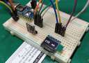
测试 为了测试电路,需要正确搭建发射端和接收端的电路。 2.5mm单声道插孔与DSLR一起使用,并经过电路操作测试。

如果您对此项目有任何疑问,请在本帖下面留下您的评论。 |