|
在不同颜色照明的项目中,WS2812系列的WS2812B是我最喜欢的RGB芯片。不久前,我注意到市场上已经有一段时间的新品了。新的RGB芯片称为WS2813,它也有不同的后缀(例如WS2813A、WS2813B、WS2813C等)。在本篇文章中,我们将对新的RGB芯片的新功能进行介绍,并提供有关基于WS2813的RGB环形灯的简短示例。
WS2813简介 根据Worldsemi的官方数据表,WS2813的第一版于2017年推出。乍一看,WS2813具有与其前代产品相同的功能:这是一种小型芯片,带有集成的多色LED可以点亮以不同的颜色显示(三种具有256级亮度的原色→对应256 * 256 * 256 = 16777216种颜色)。此外,除了GND和5V电源信号外,还可以使用单根控制线控制RGB芯片。控制线还可用于级联多个RGB芯片,以形成“ LED灯条”或“ LED环”。

与以前的版本(例如2812B)相比,WS2813的主要功能是什么? ● 双信号线:通过在“控制数据信号输入”旁边引入一个附加输入“备份控制数据信号输入”,基本上将控制线加倍。这样,如果LED条的单个RGB芯片损坏,则该损坏不会影响后续的RGB芯片。 ● 刷新频率的增加:与WS2812系列相比,刷新频率从400 Hz增加到2000 Hz。
幸运的是,现有的库(例如FastLED、Adafruit_NeoPixel)可用于控制WS2813 RGB芯片。接下来,本文提供了一个示例,展示了如何控制RGB环形灯。
示例:使用Arduino Uno控制WS2813B-Mini RGB环形灯 大多数人可能会以LED灯条的形式使用RGB芯片。或者,市场上也有LED / RGB环形灯。最近,我接触了Seeed Studio的RGB LED环形灯系列的两个模块,它们使用有WS2813B-Mini RGB芯片。在本文中,我想展示如何使用Arduino Uno控制这种RGB LED环形灯。
所需的材料清单: – Arduino Uno开发板 – 跳线 – 面包板 – RGB LED环形灯
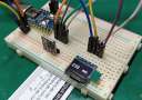
连接方式: 接线非常简单,因为只需使用三根电线即可将Arduino与LED环形灯连接。我使用了LED环形灯的Grove连接器进行连接。 Grove是Seeedstudio的许多组件可用的连接器。它使初学者可以更轻松地将组件连接到Arduino。向Arduino添加一块Grove扩展板,然后可以使用标准化的连接器在组件和扩展板之间建立连接。幸运的是,常规的跳线非常适合Grove连接器。
将Arduino的5V引脚连接到LED环形灯的VCC引脚,将Arduino的GND连接到GND,并将Arduino的数字引脚6连接到SIG。

程序设计: 以下程序演示了LED环形灯的基本的闪烁功能。该程序“遍历”每个RGB芯片并将其设置为随机颜色。如果已“遍历”所有RGB芯片,它将再次启动并用新的随机颜色覆盖现有颜色。
该程序基于FastLED库,该库安装在Arduino IDE安装中(工具->管理库…)。包括FastLED库的头文件后,必须配置可用LED的数量。实际数量取决于您的LED环形灯类型。我在代码中添加了所知道的有关LED环形灯类型的数字的注释。在setup函数中,初始化FastLED。在这里,您可以使用WS2813类型对其进行简单配置,因为FastLED的开发人员已经考虑了新的RGB芯片。 在每个loop函数调用中,索引都会递增。该索引表示设置有随机颜色的“当前” RGB芯片。如果索引大于LED环形灯上可用的RGB芯片数,则将其设置回零,然后重新开始整个过程。 - /*
- * This program demonstrates how to use RGB LED Rings. The program "walks over" each LED and sets it to a random color.
- * If you are already familiar with programming LED stripes, you will recognize that there is basically no difference.
- * The code has been written for the Ultimate RGB LED Ring v1.0, but can easily be adapted.
- *
- */
- #include "FastLED.h"
- // some LED numbers that I'm aware of...
- // Grove - RGB LED Ring (16-WS2813 Mini): 16 LEDs
- // Grove - RGB LED Ring (20-WS2813 Mini): 20 LEDs
- // Grove - RGB LED Ring (24-WS2813 Mini): 24 LEDs
- // Grove - Ultimate RGB LED Ring: 42 LEDs
- #define NUM_LEDS 42 // add number of LEDs of your RGB LED Ring here
- #define PIN_LED_RING 6 // digital output PIN that is connected to DIN of the RGB LED Ring
- #define UPDATE_TIME 250 // each 250ms, a new random color is set
- CRGB rgb_led_ring[NUM_LEDS]; // color array of the LED RGB Ring
- unsigned index = 0; // index represents the currently "walked over" LED
- void setup() {
- FastLED.addLeds<WS2813, PIN_LED_RING>(rgb_led_ring, NUM_LEDS); // Change WS2813 to something else, if your RGB LED Ring has a different chipset (e.g. WS2812B instead of WS2813).
- }
- void loop() {
- rgb_led_ring[index] = CHSV(random8(),random8(),random8()); // we set the color of the LED represented by index
- index++; // index is increased, i.e. the color of the LED to the right is set next time.
-
- FastLED.show(); // state of color array is transfered to RGB LED Ring
- if (index >= NUM_LEDS) { // if we "walked over" all LEDs, we start from the beginning again.
- index = 0;
- }
- delay(UPDATE_TIME); // program waits for 250ms
- }

编程示例2:控制两个RGB环形灯 前段时间,有网友多次询问我,当有两个LED灯条时如何应用该程序。 如果使用FastLED,则只需在setup函数中将第二个LED灯条(或LED环形灯)注册到FastLED。 我更改了先前的程序,以便能够控制两个LED环。 接线方式上,我将第二个环形灯的GND连接到Arduino的GND引脚,然后使用迷你面包板拆分Arduino的5V引脚,以便为两个环形灯共用5V连接。 最后一步,我将SIG引脚连接到Arduino的数字引脚#7。 - /*
- * This program demonstrates how to use two RGB LED Rings at the same time. For each RGB LED Ring, the program "walks over" each LED and sets it to a random color.
- * If you are already familiar with programming LED stripes, you will recognize that there is basically no difference.
- * The code has been written for the Ultimate RGB LED Ring v1.0, but can easily be adapted.
- *
- */
- #include "FastLED.h"
- // some LED numbers that I'm aware of...
- // Grove - RGB LED Ring (16-WS2813 Mini): 16 LEDs
- // Grove - RGB LED Ring (20-WS2813 Mini): 20 LEDs
- // Grove - RGB LED Ring (24-WS2813 Mini): 24 LEDs
- // Grove - Ultimate RGB LED Ring: 42 LEDs
- #define NUM_LEDS_RING1 42 // add number of LEDs of the first RGB LED Ring here
- #define NUM_LEDS_RING2 16 // add number of LEDs of the second LED Ring here
- #define PIN_LED_RING1 6 // digital output PIN that is connected to DIN of the first RGB LED Ring
- #define PIN_LED_RING2 7 // digital output PIN that is connected to DIN of the second RGB LED Ring
- #define UPDATE_TIME 250 // each 250ms, a new random color is set
- CRGB rgb_led_ring1[NUM_LEDS_RING1]; // array representing the color layout of the first ring
- CRGB rgb_led_ring2[NUM_LEDS_RING2]; // array representing the color layout of the second ring
- unsigned index_ring1 = 0; // index represents the currently "walked over" LED of the first ring
- unsigned index_ring2 = 0; // index represents the currently "walked over" LED of the second ring
- void setup() {
- FastLED.addLeds<WS2813, PIN_LED_RING1>(rgb_led_ring1, NUM_LEDS_RING1); // Change WS2813 to something else, if the first RGB LED Ring has a different chipset (e.g. WS2812B instead of WS2813).
- FastLED.addLeds<WS2813, PIN_LED_RING2>(rgb_led_ring2, NUM_LEDS_RING2); // Change WS2813 to something else, if the second RGB LED Ring has a different chipset (e.g. WS2812B instead of WS2813).
- }
- void loop() {
- rgb_led_ring1[index_ring1] = CHSV(random8(),random8(),random8()); // we set the color of the LED represented by index (first ring)
- index_ring1++; // index is increased, i.e. the color of the LED to the right is set next time.
- rgb_led_ring2[index_ring2] = CHSV(random8(),random8(),random8()); // we set the color of the LED represented by index (second ring)
- index_ring2++; // index is increased, i.e. the color of the LED to the right is set next time.
-
- FastLED.show();
- if (index_ring1 >= NUM_LEDS_RING1) { // if we "walked over" all LEDs, we start from the beginning again (first ring)
- index_ring1 = 0;
- }
- if (index_ring2 >= NUM_LEDS_RING2) { // if we "walked over" all LEDs, we start from the beginning again (second ring)
- index_ring2 = 0;
- }
- delay(UPDATE_TIME); // program waits for 250ms
- }

|