|
在本篇文章中,您将了解TCS230传感器以及如何将其与Arduino开发板一起使用来识别颜色。在本文结束时,您将找到一个创建颜色选择笔的迷人想法。使用此笔,您可以扫描周围物体的颜色,并使用该颜色开始在LCD上绘画。
什么是TSC230传感器? TSC230芯片包含一个8×8阵列的硅光电二极管,可用于识别颜色。这些光电二极管中的16个具有红色滤光器,16个具有绿色滤光器,16个具有蓝色滤光器而另外16个没有滤光器。

TCS230模块有4个白色LED灯。光电二极管从物体表面接收这些LED的反射光,然后根据它们接收的颜色产生电流。
除光电二极管外,该传感器还有一个电流 - 频率转换器。它将光电二极管产生的电流转换为频率。
该模块的输出采用方波脉冲形式,占空比为50%。
该传感器的最佳测量范围约为2至4厘米。

TCS230引脚分布 TCS230有4个控制引脚。 S0和S1用于输出频率缩放,S2和S3用于选择光电二极管的类型。 (红色、绿色、蓝色、无过滤器)


电流 - 频率转换器电路具有分频器。您可以使用S0和S1控制引脚控制此分频器。 例如,如果要测量对象中蓝色的值,则应将S2引脚状态设置为低,并将S3引脚状态设置为高电平。
所需的材料 ● Arduino UNO R3开发板 ● TCS230颜色识别传感器模块 ● 面包板 ● RGB LED灯 ● 2.4“TFT LCD显示屏 ● 公对母跳线 ● 220欧姆电阻 ● Arduino IDE

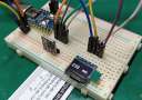
TCS239色彩传感器与Arduino的连接 如下图所示,将传感器连接到Arduino开发板。然后通过初始化引脚S0到S4来分析不同颜色的输出。

代码 以下代码测量三种颜色中每种颜色的输出信号,并在串口上显示结果。 - /*
- TCS230 color recognition sensor
- modified on 7 May 2019
- by Mohammadreza Akbari @ Electropeak
- https://electropeak.com/learn/
- Color Sensor Arduino
- ----------- --------
- VCC 5V
- GND GND
- s0 8
- s1 9
- s2 10
- s3 11
- OUT 12
- OE GND
- */
- const int s0 = 8;
- const int s1 = 9;
- const int s2 = 10;
- const int s3 = 11;
- const int out = 12;
- // LED pins connected to Arduino
- int redLed = 2;
- int greenLed = 3;
- int blueLed = 4;
- // Variables
- int red = 0;
- int green = 0;
- int blue = 0;
- void color()
- {
- digitalWrite(s2, LOW);
- digitalWrite(s3, LOW);
- //count OUT, pRed, RED
- red = pulseIn(out, digitalRead(out) == HIGH ? LOW : HIGH);
- digitalWrite(s3, HIGH);
- //count OUT, pBLUE, BLUE
- blue = pulseIn(out, digitalRead(out) == HIGH ? LOW : HIGH);
- digitalWrite(s2, HIGH);
- //count OUT, pGreen, GREEN
- green = pulseIn(out, digitalRead(out) == HIGH ? LOW : HIGH);
- }
-
- void setup()
- {
- Serial.begin(9600);
- pinMode(s0, OUTPUT);
- pinMode(s1, OUTPUT);
- pinMode(s2, OUTPUT);
- pinMode(s3, OUTPUT);
- pinMode(out, INPUT);
- pinMode(redLed, OUTPUT);
- pinMode(greenLed, OUTPUT);
- pinMode(blueLed, OUTPUT);
- digitalWrite(s0, HIGH);
- digitalWrite(s1, HIGH);
- }
-
- void loop()
- {
- color();
- Serial.print("R Intensity:");
- Serial.print(red, DEC);
- Serial.print(" G Intensity: ");
- Serial.print(green, DEC);
- Serial.print(" B Intensity : ");
- Serial.print(blue, DEC);
- //Serial.println();
- if (red < blue && red < green && red < 20)
- {
- Serial.println(" - (Red Color)");
- digitalWrite(redLed, HIGH); // Turn RED LED ON
- digitalWrite(greenLed, LOW);
- digitalWrite(blueLed, LOW);
- }
- else if (blue < red && blue < green)
- {
- Serial.println(" - (Blue Color)");
- digitalWrite(redLed, LOW);
- digitalWrite(greenLed, LOW);
- digitalWrite(blueLed, HIGH); // Turn BLUE LED ON
- }
- else if (green < red && green < blue)
- {
- Serial.println(" - (Green Color)");
- digitalWrite(redLed, LOW);
- digitalWrite(greenLed, HIGH); // Turn GREEN LED ON
- digitalWrite(blueLed, LOW);
- }
- else{
- Serial.println();
- }
- delay(300);
- digitalWrite(redLed, LOW);
- digitalWrite(greenLed, LOW);
- digitalWrite(blueLed, LOW);
- }
color()函数控制S2和S3引脚读取对象的所有颜色。此函数使用pulseln命令通过颜色传感器接收发送的脉冲。
TCS230色彩传感器校准 为了校准传感器,您需要一个白色物体。 calibrate()函数执行传感器的校准。为此,只需在串口中输入字符“c”即可。然后移除传感器周围的所有彩色物体并重新输入“c”。现在在传感器附近取一个白色物体,再次输入“c”。
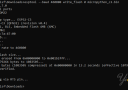
校准后,如果将白色物体放在传感器前面,则应该在串行窗口中看到三种红色,绿色和蓝色中每种颜色的值255(或大约255)。
calibrate()函数可在非彩色和白色环境中计算和存储传感器输出频率的最大和最小变化。
然后在loop函数部分中,它将颜色更改范围映射到0-255(或您定义的任何其他范围)。
代码 - /*
- // TCS230 color recognition with calibration
- modified on 7 May 2019
- by Mohammadreza Akbari @ Electropeak
- https://electropeak.com/learn/
- Color Sensor Arduino
- ----------- --------
- VCC 5V
- GND GND
- s0 8
- s1 9
- s2 10
- s3 11
- OUT 12
- OE GND
- */
- const int s0 = 8;
- const int s1 = 9;
- const int s2 = 10;
- const int s3 = 11;
- const int out = 12;
- // LED pins connected to Arduino
- int redLed = 5;
- int greenLed = 6;
- int blueLed = 3;
- // Variables
- int red = 0;
- int green = 0;
- int blue = 0;
- // Calibrated value
- int cal_min = 5;
- int cal_max_r = 50;
- int cal_max_g = 50;
- int cal_max_b = 50;
- void calibrate() {
- Serial.println("Clear sensor area. Then enter c again");
- while (Serial.read() != 'c') {
- //do nothing
- ;
- }
- color();
- cal_max_r = red;
- cal_max_g = green;
- cal_max_b = blue;
- Serial.println("Put white color infront of sensor, Then enter c again");
- while (Serial.read() != 'c') {
- //do nothing
- ;
- }
- color();
- cal_min = (red + green + blue) / 3;
- Serial.println("calibrated successfully.");
- delay(300);
- }
- void color() {
- digitalWrite(s2, LOW);
- digitalWrite(s3, LOW);
- //count OUT, pRed, RED
- red = pulseIn(out, digitalRead(out) == HIGH ? LOW : HIGH);
- digitalWrite(s3, HIGH);
- //count OUT, pBLUE, BLUE
- blue = pulseIn(out, digitalRead(out) == HIGH ? LOW : HIGH);
- digitalWrite(s2, HIGH);
- //count OUT, pGreen, GREEN
- green = pulseIn(out, digitalRead(out) == HIGH ? LOW : HIGH);
- }
- void setup()
- {
- Serial.begin(9600);
- pinMode(s0, OUTPUT);
- pinMode(s1, OUTPUT);
- pinMode(s2, OUTPUT);
- pinMode(s3, OUTPUT);
- pinMode(out, INPUT);
- pinMode(redLed, OUTPUT);
- pinMode(greenLed, OUTPUT);
- pinMode(blueLed, OUTPUT);
- digitalWrite(s0, HIGH);
- digitalWrite(s1, HIGH);
- }
- void loop()
- {
- color();
- if (Serial.read() == 'c') {
- calibrate();
- }
- red = map(red, cal_min, cal_max_r, 255, 0);
- green = map(green, cal_min, cal_max_g, 255, 0);
- blue = map(blue, cal_min, cal_max_b, 255, 0);
- Serial.print("R Intensity:");
- Serial.print(red);
- Serial.print(" G Intensity: ");
- Serial.print(green);
- Serial.print(" B Intensity : ");
- Serial.println(blue);
- delay(200);
- }
使用TCS230传感器和Arduino制作拾色笔 如果使用Arduino UNO,则必须使用电线将颜色传感器引脚焊接到Arduino板上。 但是如果你使用Arduino MEGA,你可以使用电路板的最后一个引脚将颜色传感器连接到它。 以下代码在LCD上创建绘画页面。 笔的默认颜色为红色。 按住键并将颜色传感器关闭到所需对象以选择其颜色。 然后笔的颜色会变为该对象的颜色。
电路

代码 - /*
- TCS230 color picker + paint
- Modified on 8 May 2019
- By Mohammadreza Akbari @ Electropeak
- https://electropeak.com/learn/
- Color Sensor Arduino
- ----------- --------
- VCC 5V
- GND GND
- s0 5V
- s1 5V
- s2 10
- s3 11
- OUT 12
- OE GND
- */
- #include <Adafruit_GFX.h> // Core graphics library
- #include <Adafruit_TFTLCD.h> // Hardware-specific library
- #include <TouchScreen.h>
- #if defined(__SAM3X8E__)
- #undef __FlashStringHelper::F(string_literal)
- #define F(string_literal) string_literal
- #endif
- //LCD
- #define YP A3 // must be an analog pin, use "An" notation!
- #define XM A2 // must be an analog pin, use "An" notation!
- #define YM 9 // can be a digital pin
- #define XP 8 // can be a digital pin
- #define TS_MINX 150
- #define TS_MINY 120
- #define TS_MAXX 920
- #define TS_MAXY 940
- // For better pressure precision, we need to know the resistance
- // between X+ and X- Use any multimeter to read it
- // For the one we're using, its 300 ohms across the X plate
- TouchScreen ts = TouchScreen(XP, YP, XM, YM, 300);
- #define LCD_CS A3
- #define LCD_CD A2
- #define LCD_WR A1
- #define LCD_RD A0
- // optional
- #define LCD_RESET A4
- // Assign human-readable names to some common 16-bit color values:
- #define BLACK 0x0000
- #define BLUE 0x001F
- #define RED 0xF800
- #define GREEN 0x07E0
- #define CYAN 0x07FF
- #define MAGENTA 0xF81F
- #define YELLOW 0xFFE0
- #define WHITE 0xFFFF
- Adafruit_TFTLCD tft(LCD_CS, LCD_CD, LCD_WR, LCD_RD, LCD_RESET);
- #define BOXSIZE 40
- #define PENRADIUS 3
- int oldcolor, ccolor;
- #define MINPRESSURE 10
- #define MAXPRESSURE 1000
- //Color sensor
- const int s2 = 10;
- const int s3 = 11;
- const int out = 12;
- const int button = 13;
- // Color variables
- int red = 0;
- int green = 0;
- int blue = 0;
- // Calibrated value
- int cal_min = 5;
- int cal_max_r = 50;
- int cal_max_g = 50;
- int cal_max_b = 50;
- uint16_t my_color;
- void calibrate() {
- Serial.println("Clear sensor area. Then enter c again");
- while (Serial.read() != 'c') {
- //do nothing
- ;
- }
- color();
- cal_max_r = red;
- cal_max_g = green;
- cal_max_b = blue;
- Serial.println("Put white color infront of sensor, Then enter c again");
- while (Serial.read() != 'c') {
- //do nothing
- ;
- }
- color();
- cal_min = (red + green + blue) / 3;
- Serial.println("calibrated successfully.");
- delay(300);
- }
- void color() {
- digitalWrite(s2, LOW);
- digitalWrite(s3, LOW);
- //count OUT, pRed, RED
- red = pulseIn(out, digitalRead(out) == HIGH ? LOW : HIGH);
- digitalWrite(s3, HIGH);
- //count OUT, pBLUE, BLUE
- blue = pulseIn(out, digitalRead(out) == HIGH ? LOW : HIGH);
- digitalWrite(s2, HIGH);
- //count OUT, pGreen, GREEN
- green = pulseIn(out, digitalRead(out) == HIGH ? LOW : HIGH);
- }
- void pick_color() {
- color();
- red = map(red, cal_min, cal_max_r, 255, 0);
- green = map(green, cal_min, cal_max_g, 255, 0);
- blue = map(blue, cal_min, cal_max_b, 255, 0);
- Serial.print("R Intensity:");
- Serial.print(red);
- Serial.print(" G Intensity: ");
- Serial.print(green);
- Serial.print(" B Intensity : ");
- Serial.println(blue);
- //my_color = tft.color565(abs(255 - red), abs(255 - green), abs(255 - blue));
- my_color = tft.color565(red, green, blue);
- tft.fillRect(0, 0, 6*BOXSIZE, BOXSIZE, my_color);
-
- delay(100);
- }
- void setup()
- {
- Serial.begin(9600);
- tft.reset();
- delay(1000);
- uint16_t identifier = tft.readID();
- if (identifier == 0x9325) {
- Serial.println(F("Found ILI9325 LCD driver"));
- } else if (identifier == 0x9328) {
- Serial.println(F("Found ILI9328 LCD driver"));
- } else if (identifier == 0x7575) {
- Serial.println(F("Found HX8347G LCD driver"));
- } else if (identifier == 0x9341) {
- Serial.println(F("Found ILI9341 LCD driver"));
- } else if (identifier == 0x8357) {
- Serial.println(F("Found HX8357D LCD driver"));
- } else {
- Serial.print(F("Unknown LCD driver chip: "));
- Serial.println(identifier, HEX);
- Serial.println(F("If using the Adafruit 2.8" TFT Arduino shield, the line:"));
- Serial.println(F("#define USE_ADAFRUIT_SHIELD_PINOUT"));
- Serial.println(F("should appear in the library header (Adafruit_TFT.h)."));
- Serial.println(F("If using the breakout board, it should NOT be #defined!"));
- Serial.println(F("Also if using the breakout, double-check that all wiring"));
- Serial.println(F("matches the tutorial."));
- return;
- }
- tft.begin(identifier);
- tft.fillScreen(BLACK);
- tft.fillRect(0, 0, 6*BOXSIZE, BOXSIZE, RED);
- my_color = RED;
- pinMode(s2, OUTPUT);
- pinMode(s3, OUTPUT);
- pinMode(out, INPUT);
- pinMode(button, INPUT_PULLUP);
- }
- void loop()
- {
- if (Serial.read() == 'c') {
- calibrate();
- }
- while (digitalRead(button) == LOW) {
- pick_color();
- }
- TSPoint p = ts.getPoint();
- // if sharing pins, you'll need to fix the directions of the touchscreen pins
- //pinMode(XP, OUTPUT);
- pinMode(XM, OUTPUT);
- pinMode(YP, OUTPUT);
- //pinMode(YM, OUTPUT);
- // we have some minimum pressure we consider 'valid'
- // pressure of 0 means no pressing!
- if (p.z > MINPRESSURE && p.z < MAXPRESSURE) {
- /*
- Serial.print("X = "); Serial.print(p.x);
- Serial.print("\tY = "); Serial.print(p.y);
- Serial.print("\tPressure = "); Serial.println(p.z);
- */
-
- if (p.y < (TS_MINY-5)) {
- Serial.println("erase");
- // press the bottom of the screen to erase
- tft.fillRect(0, BOXSIZE, tft.width(), tft.height()-BOXSIZE, BLACK);
- }
- // scale from 0->1023 to tft.width
- p.x = map(p.x, TS_MINX, TS_MAXX, tft.width(), 0);
- p.y = map(p.y, TS_MINY, TS_MAXY, tft.height(), 0);
- /*
- Serial.print("("); Serial.print(p.x);
- Serial.print(", "); Serial.print(p.y);
- Serial.println(")");
- */
-
- if (((p.y-PENRADIUS) > BOXSIZE) && ((p.y+PENRADIUS) < tft.height())) {
- tft.fillCircle(p.x, p.y, PENRADIUS, my_color);
- }
- }
- }
当按键按下时调用pick_color函数。 它读取位于传感器附近的物体的颜色,并将笔颜色更改为该颜色。
以上就是本文的全部内容,如有问题,请随时在本帖下面进行回复。 |