|
在本篇文章中,我们将学习如何使用Arduino开发板和颜色传感器TCS230 / TCS3200来检测颜色。
色彩传感器TCS230的工作原理 TCS230通过内部的8 x 8光电二极管阵列感应彩色光线。然后使用电流 - 频率转换器将来自光电二极管的读数转换成方波,其频率与光强度成正比。最后,我们可以使用Arduino开发板读取方波输出并获得颜色的结果。

如果我们仔细观察传感器,我们可以看到它如何检测各种颜色。光电二极管具有三种不同的滤色器。其中,16个有红色滤光片,另外16个有绿色滤光片,另外16个有蓝色滤光片,另外16个光电二极管是透明的,没有滤光片。

每16个光电二极管并联连接,因此使用两个控制引脚S2和S3,我们可以选择读取哪个。因此,例如,如果我们想要检测红色,我们可以通过根据表格将两个引脚设置为低逻辑电平来使用16个红色滤波光电二极管。

传感器还有两个控制引脚S0和S1,用于缩放输出频率。频率可以缩放到三个不同的预设值100%、20%或2%。这种频率调整功能允许传感器的输出针对各种频率计数器或微控制器进行优化。
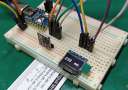
现在我们可以继续学习,将TCS230传感器连接到Arduino开发板。以下是电路连接的原理图。

该连接图所需的组件如下所示:
● 色彩传感器TCS230 / TCS3200 ● Arduino开发板 ● 面包板和跳线
TCS230颜色传感器源代码 代码描述:首先,我们需要定义传感器所连接的引脚,并定义一个用于读取频率的变量。在setup函数部分,我们需要将四个控制引脚定义为输出,将传感器输出定义为Arduino输入。这里我们还需要设置频率调整,在本例中我将其设置为20%,然后启动串行通信以在串行监视器中显示结果。
在loop()函数部分,我们首先读取红色滤光光电二极管。为此,我们将两个控制引脚S2和S3设置为低逻辑电平。然后使用“pulseIn()”函数,我们将读取输出频率并将该值放到变量“frequency”中。使用Serial.print()函数,我们将在串行监视器上打印结果。对于其他两种颜色也采用相同的步骤,我们只需要调整控制引脚以获得适当的颜色。 - /* Arduino Color Sensing Tutorial
- *
- * by Dejan Nedelkovski, www.HowToMechatronics.com
- *
- */
-
- #define S0 4
- #define S1 5
- #define S2 6
- #define S3 7
- #define sensorOut 8
- int frequency = 0;
- void setup() {
- pinMode(S0, OUTPUT);
- pinMode(S1, OUTPUT);
- pinMode(S2, OUTPUT);
- pinMode(S3, OUTPUT);
- pinMode(sensorOut, INPUT);
-
- // Setting frequency-scaling to 20%
- digitalWrite(S0,HIGH);
- digitalWrite(S1,LOW);
-
- Serial.begin(9600);
- }
- void loop() {
- // Setting red filtered photodiodes to be read
- digitalWrite(S2,LOW);
- digitalWrite(S3,LOW);
- // Reading the output frequency
- frequency = pulseIn(sensorOut, LOW);
- // Printing the value on the serial monitor
- Serial.print("R= ");//printing name
- Serial.print(frequency);//printing RED color frequency
- Serial.print(" ");
- delay(100);
- // Setting Green filtered photodiodes to be read
- digitalWrite(S2,HIGH);
- digitalWrite(S3,HIGH);
- // Reading the output frequency
- frequency = pulseIn(sensorOut, LOW);
- // Printing the value on the serial monitor
- Serial.print("G= ");//printing name
- Serial.print(frequency);//printing RED color frequency
- Serial.print(" ");
- delay(100);
- // Setting Blue filtered photodiodes to be read
- digitalWrite(S2,LOW);
- digitalWrite(S3,HIGH);
- // Reading the output frequency
- frequency = pulseIn(sensorOut, LOW);
- // Printing the value on the serial monitor
- Serial.print("B= ");//printing name
- Serial.print(frequency);//printing RED color frequency
- Serial.println(" ");
- delay(100);
- }
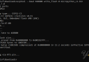
现在,如果我们运行串行监视器,我们将开始获取一些值。这些值取决于所选的频率缩放以及周围的亮度。

请注意,由于每个光电二极管类型的灵敏度不同,三个值不同,正如传感器数据表中的光电二极管光谱响应度图中所示。
然而,现在让我们看看当在传感器前面放置不同的颜色时,这些值会如何反应。例如,如果选择红色,初始值将下降,本例中从大约70下降到大约25。

所以现在如果我们想用0到255的RGB模型表示检测到的颜色,我们使用map()函数将读数映射或转换为0到255之间的值。 - //Remaping the value of the frequency to the RGB Model of 0 to 255
- frequency = map(frequency, 25,70,255,0);
值70将映射到0,值25映射到255。相同的过程适用于其他两种颜色。
以下是此示例的最终源代码: - /* Arduino Color Sensing Tutorial
- *
- * by Dejan Nedelkovski, www.HowToMechatronics.com
- *
- */
-
- #define S0 4
- #define S1 5
- #define S2 6
- #define S3 7
- #define sensorOut 8
- int frequency = 0;
- void setup() {
- pinMode(S0, OUTPUT);
- pinMode(S1, OUTPUT);
- pinMode(S2, OUTPUT);
- pinMode(S3, OUTPUT);
- pinMode(sensorOut, INPUT);
-
- // Setting frequency-scaling to 20%
- digitalWrite(S0,HIGH);
- digitalWrite(S1,LOW);
-
- Serial.begin(9600);
- }
- void loop() {
- // Setting red filtered photodiodes to be read
- digitalWrite(S2,LOW);
- digitalWrite(S3,LOW);
- // Reading the output frequency
- frequency = pulseIn(sensorOut, LOW);
- //Remaping the value of the frequency to the RGB Model of 0 to 255
- frequency = map(frequency, 25,72,255,0);
- // Printing the value on the serial monitor
- Serial.print("R= ");//printing name
- Serial.print(frequency);//printing RED color frequency
- Serial.print(" ");
- delay(100);
- // Setting Green filtered photodiodes to be read
- digitalWrite(S2,HIGH);
- digitalWrite(S3,HIGH);
- // Reading the output frequency
- frequency = pulseIn(sensorOut, LOW);
- //Remaping the value of the frequency to the RGB Model of 0 to 255
- frequency = map(frequency, 30,90,255,0);
- // Printing the value on the serial monitor
- Serial.print("G= ");//printing name
- Serial.print(frequency);//printing RED color frequency
- Serial.print(" ");
- delay(100);
- // Setting Blue filtered photodiodes to be read
- digitalWrite(S2,LOW);
- digitalWrite(S3,HIGH);
- // Reading the output frequency
- frequency = pulseIn(sensorOut, LOW);
- //Remaping the value of the frequency to the RGB Model of 0 to 255
- frequency = map(frequency, 25,70,255,0);
- // Printing the value on the serial monitor
- Serial.print("B= ");//printing name
- Serial.print(frequency);//printing RED color frequency
- Serial.println(" ");
- delay(100);
- }
请注意,颜色不是那么准确,但对于简单的项目来说它们仍然足够好。 作为TCS230颜色传感器的另一个例子,我们将学习如何制作Arduino自动颜色分选机。

以上就是本篇文章的全部内容,如果遇到任何问题,请随时在下面进行回复。 |