|
本篇文章主要介绍如何使用PIC单片机从DHT11读取湿度和温度,并将其显示在LCD显示屏上。在这个例子中,我们使用的单片机型号是PIC16F628A。
所需的内容 要完成此项目,您需要以下内容:
● 使用安装有Microchip MPLAB X IDE和XC8 v1.34编译器的计算机。
● PIC16F628单片机 ● LCD(HD4480或类似产品) ● DHT11传感器 ● PICkit3烧写器 ● 面包板和一些连接导线。
简介 DHT11是一个湿度和温度传感器,使用一根导线发送40位数据。 前16位是湿度的整数和小数,接下来的16位是整数和温度的分数,最后8位是校验和。
要让DHT11和MCU相互通讯,需要同步它们。为了使它们同步,MCU在数据引脚上发送一个20us高脉冲的启动信号。在脉冲之后,MCU等待接收数据。在软件中,我们必须改变数据引脚的方向。您可以采用4引脚和3引脚布局的传感器,但我们使用的是3引脚版本。两者的性能没有区别,多余的引脚没有连接到任何东西。

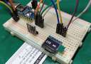
硬件 制作小工具时要做的第一件事就是制作一个方块图。通过这种方式,您可以忽略您想要的以及您想要的方式。这是我们的小工具的框图:

◼ 我们希望DHT11将数据发送到MCU。
◼ 我们希望MCU处理数据并将其显示在LCD上。 ◼ 我们希望能够使用ICSP对MCU进行编程。
原理图布局 原理图布局分为块:

Powerblock - 将电源调节到5伏。它使用的是LM7805。 ICSP - 这是一个1x5引脚接头,连接到MCU的编程引脚。我们使用此插头对MCU进行编程。 DHT11 - 这是一个1x3引脚接头,用于固定传感器。中间引脚连接到MCU,用于数据传输。 MCU - 这是PIC16F628A,它从DHT11接收数据并将其显示在LCD上 LCD - 这是一个16x02 LCD,显示湿度和温度。
我们正在使用MCU的内部4MHz振荡器。因此,电路中没有晶体或陶瓷谐振器。
软件 安装XC8编译器时,还安装了一些头文件和源文件。 在本篇文章中,我们使用了XC8编译器附带的LCD文件:XLCD.H和一堆源文件。 为了使事情变得更容易,我将所有源文件复制到一个文件中。 在我的Ubuntu安装中,我找到了XLCD源文件:
- /opt/microchip/xc8/v1.34/sources/pic18/plib/XLCD
那里有10个文件,bysyxlcd.c、openxlcd.c、putrxlcd.c等等。 我将所有这些文件放在一个文件中,并将其命名为my_xlcd.c。 此文件现在包含所有函数。 myxlcd.c文件和xlcd.h文件被复制到项目文件夹中。 (xlcd.h文件位于:/opt/microchip/xc8/v1.34/include/plib)。 xlcd.h文件是一个标准文件,需要进行一些编辑。 我们需要更改MCU引脚的连接以匹配我们的设置: - /* DATA_PORT defines the port to which the LCD data lines are connected */
- #define DATA_PORT PORTB
- #define TRIS_DATA_PORT TRISB
- /* CTRL_PORT defines the port where the control lines are connected.
- * These are just samples, change to match your application.
- */
- #define RW_PIN PORTAbits.RA0 /* PORT for RW */
- #define TRIS_RW TRISAbits.TRISA0 /* TRIS for RW */
- #define RS_PIN PORTAbits.RA1 /* PORT for RS */
- #define TRIS_RS TRISAbits.TRISA1 /* TRIS for RS */
- #define E_PIN PORTAbits.RA7 /* PORT for D */
- #define TRIS_E TRISAbits.TRISA7 /* TRIS for E */
这里,定义了LCD和MCU之间的连接。 这两个文件没有更多内容。 (my_xlcd.h和my_xlcd.c)
接下来是主程序。 它开始是一些INCLUDES、配置位、定义、变量和函数原型: - // INCLUDES
- #include <stdio.h> // Including Standard Input / Outputlibrary
- #include <stdlib.h> // Including Standard library function
- #include <xc.h> // Including XC8 compiler library
- #include "my_xlcd.h" // Including my custom LCD
- // CONFIG
- #pragma config FOSC = INTOSCIO // Oscillator Selection bits (INTRC oscillator: I/O function on RA6/OSC2/CLKOUT pin, I/O function on RA7/OSC1/CLKIN)
- #pragma config WDTE = OFF // Watchdog Timer Enable bit (WDT disabled)
- #pragma config PWRTE = ON // Power-up Timer Enable bit (PWRT enabled)
- #pragma config MCLRE = ON // RA5/MCLR pin function select (RA5/MCLR pin function is MCLR)
- #pragma config BOREN = ON // Brown-out Reset Enable bit (BOD Reset enabled)
- #pragma config LVP = ON // Low-Voltage Programming Enable bit (RB4/PGM pin has PGM function, low-voltage programming enabled)
- #pragma config CPD = OFF // Data Code Protection bit (Data memory code protection off)
- #pragma config CP = OFF // Code Protection bits (Program memory code protection off)
- // DEFINES
- #define _XTAL_FREQ 4000000 // Telling the compiler, that we are using 4MHz
- #define data PORTAbits.RA2 // Defining RA0 as datapin
- #define data_dir TRISAbits.TRISA2 // Definig TRISA0 as dataport
- // GLOBAL VARIABLES
- char message1[] = "Temp = 00.0 c";
- char message2[] = "RH = 00.0 %";
- unsigned short TOUT = 0, CheckSum, i;
- unsigned short T_Byte1, T_Byte2, RH_Byte1, RH_Byte2;
- // PROTOTYES
- void init_XLCD(void);
- void DelayFor18TCY(void);
- void DelayPORXLCD(void);
- void DelayXLCD(void);
- void Delay10KTCYx(unsigned char);
- void StartSignal(void);
- unsigned short ReadByte();
- unsigned short CheckResponse();
然后我们开始写相关函数。 为了使LCD与MCU一起工作,我们需要写一些延迟函数。 在XLCD.H文件的顶部,声明: * - 用户必须提供三个延迟例程: * - DelayFor18TCY()提供18 Tcy的延迟 * - DelayPORXLCD()提供至少15ms的延迟 * - DelayXLCD()提供至少5ms的延迟
我们需要添加第四个延迟函数,Delay10KTCYx
以下是LCD的初始化函数和延迟函数: - // FUNCTIONS
- void init_XLCD(void){
- OpenXLCD(FOUR_BIT & LINES_5X7); // Sets 4-bit & 5x7 charachters
- while(BusyXLCD()); // Checks if LCD is busy
- WriteCmdXLCD(0x06); // Moves cursor right
- WriteCmdXLCD(0x0C); // Display on, cursor off
- }
- void DelayFor18TCY(void){ // as it says in the XLCD.H file
- NOP(); NOP(); NOP(); NOP(); NOP(); NOP(); NOP();
- NOP(); NOP(); NOP(); NOP(); NOP(); NOP(); NOP();
- return;
- }
- void DelayPORXLCD(void){ // as it says in the XLCD.H file
- __delay_ms(15);
- }
- void DelayXLCD(void){ // as it says in the XLCD.H file
- __delay_ms(5);
- }
- void Delay10KTCYx(unsigned char){ // as it says in the XLCD.H file
- __delay_ms(10);
- }
接下来是Start signal、Readbyte和CheckResponse函数: - void StartSignal(){
- data_dir = 0; // Sets TRISA2 to output
- data = 0; // Set RA2 to LOW
- __delay_ms(18); // Waits for 18 ms
- data = 1; // Sets RA2 HIGH
- __delay_us(20); // Waits for 20 ms
- data_dir = 1; // Sets TRISA2 to input
- }
- unsigned short ReadByte(){
- unsigned short num = 0, t;
- data_dir = 1; // Sets TRISA2 to input
- for (i=0;i<8;i++){ // Start loop
- while(!data); // When data is not valid
- TMR2 = 0; // Sets TMR2 to 0
- T2CONbits.TMR2ON = 1; // Start TMR2 from 0 when a low to high data pulse
- while(data); // is detected, and wait until it falls low again
- T2CONbits.TMR2ON = 0; // Stop the TMR2 when the data pulse falls low
- if(TMR2>40) num |= 1 << (7-i); // If time > 40us, data is 1
- }
- return num; // Return 8-bit = 1-byte
- }
- unsigned short CheckResponse(){
- TOUT = 0;
- TMR2 = 0;
- T2CONbits.TMR2ON = 1; // Turn on TMR2
- while(!data && !TOUT); // While NOT data and NOT TOUT
- if (TOUT) return 0; // Return 0 => OK
- else {
- TMR2 = 0; // Disable Timer 2
- while(data && !TOUT); // While data and NOT TOUT
- if(TOUT) return 0; // If Tout = 1 then return 0 => OK
- else {
- T2CONbits.TMR2ON = 0; // Turn off TMR2
- return 1; // Return 1 => NOT OK
- }
- }
- }
为了掌握MCU何时发送启动信号,以及当DHT11完成40位时,我们需要一个中断函数: - void interrupt tc_int(void){
- if(PIR1bits.TMR2IF){ // If TMR2 to PR2 match Interrupt Flag
- TOUT = 1;
- T2CONbits.TMR2ON = 0; // Stop timer
- PIR1bits.TMR2IF = 0; // Clear TMR0 interrupt flag
- }
- }
最后我们需要main程序: - int main(int argc, char** argv) {
- unsigned short check;
- TRISB = 0b00000000; // TRISB output
- PORTB = 0b00000000; // PORTB low
- TRISA = 0b00000001; // TRISA output
- PORTA = 0b00000000; // PORTA low
-
- CMCON = 0x07; // Comparators off
-
- // TIMER
- INTCONbits.GIE = 1; // Enable global interrupt
- INTCONbits.PEIE = 1; // Enable peripheral interrupt
- PIE1bits.TMR2IE = 1; // Enable Timer2 interrupt
- T2CON = 0; // Prescaler 1:1 and Timer2 is off initially
- PIR1bits.TMR2IF = 0; // Clear TMR INT flag bit
- TMR2 = 0;
-
- init_XLCD(); // Initialize the LCD
- putrsXLCD(" Hello World."); // Welcome text
- SetDDRamAddr(0x40); // Move cursor to line 2
- putrsXLCD(" I'm alive.");
- __delay_ms(250);
- do {
- __delay_ms(1000);
- StartSignal(); // Send the Startsignal
- check = CheckResponse(); // Assign check with 0 = OK, or 1 = NOT OK
- if(!check) { // OK check = 1 => NOT OK
- WriteCmdXLCD(0x01); // Clear screen, set cursor in 0,0
- putrsXLCD("No response."); // Write error message
- SetDDRamAddr(0x40);
- putrsXLCD("Please check.");
- }
- else { // IF chack = 0 => OK
-
- RH_Byte1 = ReadByte(); // Read first byte
- RH_Byte2 = ReadByte(); // Read second byte
- T_Byte1 = ReadByte(); // Read third byte
- T_Byte2 = ReadByte(); // Read fourth byte
- CheckSum = ReadByte(); // Read checksum
- // Checks if all bytes is equal to the checksum
- if (CheckSum == ((RH_Byte1 + RH_Byte2 + T_Byte1 + T_Byte2) & 0xFF))
- {
- message1[7] = T_Byte1/10 + 48; // Extract the tens place
- message1[8] = T_Byte1 + 48; // Extract the ones place
- message1[10]= T_Byte2/10 + 48; // Extract the decimal
- message1[11] = 223; // ASCII code for degree symbol
- message2[7] = RH_Byte1/10 + 48; // Extract the tens place
- message2[8] = RH_Byte1 + 48; // Extract the ones place
- message2[10] = RH_Byte2/10 + 48; // Extract the decimal
- WriteCmdXLCD(0x01);
- putrsXLCD(message1); // Write the temp to LCD
- SetDDRamAddr(0x40);
- putrsXLCD(message2); // Write the humidity to LCD
- }
- else { // Checksum is not correct
- WriteCmdXLCD(0x01);
- putrsXLCD("Checksum error!");
- SetDDRamAddr(0x40);
- putrsXLCD("Please wait.");
- }
- }
- } while (1); // Do it forever.
- }
以上是使用PIC单片机读取DHT11数据的一种方法。


总结
我们使用PIC16F628A单片机读取DHT11温湿度传感器,然后在LCD上显示温度和湿度。 您可以通过一些代码调整以适合您喜欢的MCU。
|