风筝
发表于: 2023-2-23 14:18:56 | 显示全部楼层

由于RFID技术的发展,人们在超市结账时排长队的日子已经一去不复返了。 借助基于RFID的穿行式自动结账解决方案,您可以装满购物车并直接走出门外。 您不再需要等待有人将您购物车中的每件商品一一结账; 现在,借助附在物品上的RFID标签,购物车中的每件物品几乎都能立即被检测到。


对于大多数基于RFID的Arduino项目,RC522 RFID读写器模块是一个不错的选择。 它功耗低、成本低、非常坚固、易于连接并且在爱好者中非常受欢迎。


什么是RFID技术及其工作原理?

RFID或射频识别系统(Radio Frequency Identification)由两个主要组件组成,一个是贴在待识别物体上的标签,另一个是读取标签的读卡器。


读卡器由射频模块和产生高频电磁场的天线组成。 而标签通常是无源设备(它没有电池)。 它由一个存储和处理信息的微芯片,以及一个用于接收和发射信号的天线组成。

How-RFID-Technology-Works-Reader-Writer-System-Tag-Communication.png


当标签靠近读卡器时,读卡器会产生电磁场。 这会导致电子穿过标签的天线并随后为芯片供电。


然后芯片通过将其存储的信息以另一种无线电信号的形式发送回读卡器来做出响应。 这称为反向散射。读卡器检测并解析这种反向散射并将数据发送到计算机或微控制器。


硬件概述

基于NXP的MFRC522芯片的RC522 RFID模块是您可以在网上买到的最便宜的RFID之一。 它通常带有一个RFID卡标签和一个具有1KB内存的密钥卡标签。 它的优势在于可以编写一个标签,这意味着您可以在其中存储任何消息。

RC522-RFID-Reader-Writer-Module-with-Tag-Card-and-FOB-Key-Tag.png


RC522 RFID读取器模块旨在创建13.56MHz电磁场并与RFID标签(ISO 14443A 标准标签)通信。读卡器可以通过4针SPI与微控制器通信,最大数据速率为10 Mbps。 它还支持通过I2C和UART协议进行通信。


RC522 RFID模块可以被编程为产生中断,允许模块在标签接近它时提醒我们,而不是不断地询问模块“附近有卡吗?”。


该模块的工作电压范围为2.5至3.3V,好消息是逻辑引脚可承受5V电压,因此我们可以轻松地将它连接到Arduino或任何5V逻辑微控制器,而无需使用逻辑电平转换器。


RC522 RFID射频模块的引脚分布

RC522模块共有8个引脚连接到外部。 连接如下:

RC522-RFID-Reader-Writer-Module-Pinout.png

VCC 为模块供电。 这可以是2.5到3.3V之间的任何值。 您可以将它连接到Arduino的3.3V输出。

RST 是用于复位和断电的输入。 当此引脚变低时,模块进入掉电模式。 其中振荡器关闭,输入引脚与外界断开。 而模块在信号的上升沿复位。

GND 是接地引脚,需要连接到Arduino上的GND引脚。

IRQ 是一个中断引脚,当附近有RFID标签时,它会向微控制器发出中断信号。

MISO / SCL / Tx 引脚在启用SPI接口时充当主输入从输出,在启用I2C接口时充当串行时钟,在启用UART接口时充当串行数据输出。

MOSI(Master Out Slave In)是RC522模块的SPI输入。

SCK(串行时钟)接受SPI总线主机(即 Arduino)提供的时钟脉冲。

SS / SDA / Rx 引脚在启用SPI接口时用作信号输入,在启用I2C接口时用作串行数据,在启用UART接口时用作串行数据输入。


将RC522 RFID模块连接到Arduino开发板

现在我们了解了关于模块的一切,让开始将它连接到我们的Arduino吧!


首先将模块上的VCC引脚连接到3.3V,并将GND引脚连接到Arduino上的GND。RST可以连接到Arduino上的任何数字引脚。在例子中,它连接到数字引脚#5。 IRQ引脚未连接,因为我们将要使用的Arduino库不支持它。


现在我们只剩下用于SPI通信的引脚。 由于RC522模块需要大量数据传输,因此当连接到微控制器上的硬件SPI引脚时,它们将提供最佳性能。

Arduino-Wiring-Fritzing-Connections-with-RC522-RFID-Reader-Writer-Module.png


连接好一切后,您就可以开始了!


安装库

与 RC522 RFID模块通信需要大量工作,但对我们来说幸运的是,有一个MFRC522库的库可以让读写RFID标签变得简单。


该库未包含在Arduino IDE中,因此您需要先安装它。


要安装库,请导航至 Sketch > Include Libraries > Manage Libraries…等待库管理器下载库索引并更新已安装库的列表。

Manage-Libraries.png


通过输入“mfrc522”筛选搜索。 查找GithubCommunity提供的库文件。 单击该条目,然后选择安装。

MFRC522-Library-Installation.png


Arduino 代码 —— 读取RFID标签

安装库后,打开示例子菜单并选择 MFRC522 > DumpInfo 示例草图。

MFRC522-Library-Sketch-DumpInfo.png


这个草图只是读取标签并显示存储在其中的信息。 在尝试任何新标签之前,此草图非常方便!


转到草图的开头并确保RST_PIN已正确初始化,在例子中,我们使用的是数字引脚#5,因此将其更改为 5。


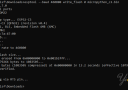
现在上传草图并打开串口监视器。 当你把标签靠近模块时,你会得到类似下面的东西。 在显示所有信息之前,请勿移动标签。

MFRC522-Library-DumpInfo-Output.png


它显示了有关标签的所有有用信息,包括标签的唯一 ID (UID)、内存大小和整个1K内存。


MIFARE Classic 1K 内存布局

标签的1K内存被分成16个扇区(从0到15)。 每个扇区进一步分为4个块(块0到3)。 每个块可以存储16个字节的数据(从0到15)。


所以我们有:

16 个扇区 x 4 个块 x 16 字节数据 = 1024 字节 = 1K 内存


整个1K内存以及扇区、块和数据在下面突出显示。

MFRC522-Library-DumpInfo-Memory-Layout.png


这是 MIFARE Classic 1K 内存映射布局的 3D 表示。

3D-Representation-MIFARE-Classic-1K-Memory-Map-Layout.png


每个扇区的最后一个块称为扇区尾部。 它包含称为访问位的信息,这些信息提供对该扇区中剩余块的读写访问。 这意味着每个扇区只有3个块(块 #0、#1 和 #2)实际上是可写的,换句话说,每个扇区只有48个字节可供使用。


扇区#0的块#0也称为制造商块,其中包含IC 制造商数据和唯一标识符 (UID)。 制造商块以红色突出显示。


跳转到指定楼层
风筝
发表于: 2023-2-23 14:20:26 | 显示全部楼层

Arduino 代码 —— 写RFID标签

假设您已成功读取RFID标签,我们将继续进行下一个实验。 以下草图演示了将自定义数据写入RFID标签。 在我们开始对其进行详细分析之前,请使用以下草图代码。

  1. #include <SPI.h>      //include the SPI bus library
  2. #include <MFRC522.h>  //include the RFID reader library

  3. #define SS_PIN 10  //slave select pin
  4. #define RST_PIN 5  //reset pin

  5. MFRC522 mfrc522(SS_PIN, RST_PIN);  // instatiate a MFRC522 reader object.
  6. MFRC522::MIFARE_Key key;          //create a MIFARE_Key struct named 'key', which will hold the card information

  7. //this is the block number we will write into and then read.
  8. int block=2;  

  9. byte blockcontent[16] = {"Last-Minute-Engg"};  //an array with 16 bytes to be written into one of the 64 card blocks is defined
  10. //byte blockcontent[16] = {0,0,0,0,0,0,0,0,0,0,0,0,0,0,0,0};  //all zeros. This can be used to delete a block.

  11. //This array is used for reading out a block.
  12. byte readbackblock[18];

  13. void setup()
  14. {
  15.     Serial.begin(9600);        // Initialize serial communications with the PC
  16.     SPI.begin();               // Init SPI bus
  17.     mfrc522.PCD_Init();        // Init MFRC522 card (in case you wonder what PCD means: proximity coupling device)
  18.     Serial.println("Scan a MIFARE Classic card");
  19.   
  20.   // Prepare the security key for the read and write functions.
  21.   for (byte i = 0; i < 6; i++) {
  22.     key.keyByte[i] = 0xFF;  //keyByte is defined in the "MIFARE_Key" 'struct' definition in the .h file of the library
  23.   }
  24. }

  25. void loop()
  26. {  
  27.   // Look for new cards
  28.   if ( ! mfrc522.PICC_IsNewCardPresent()) {
  29.     return;
  30.   }
  31.   
  32.   // Select one of the cards
  33.   if ( ! mfrc522.PICC_ReadCardSerial())
  34.   {
  35.     return;
  36.   }
  37.     Serial.println("card selected");
  38.          
  39.    //the blockcontent array is written into the card block
  40.    writeBlock(block, blockcontent);
  41.    
  42.    //read the block back
  43.    readBlock(block, readbackblock);
  44.    //uncomment below line if you want to see the entire 1k memory with the block written into it.
  45.    //mfrc522.PICC_DumpToSerial(&(mfrc522.uid));
  46.    
  47.    //print the block contents
  48.    Serial.print("read block: ");
  49.    for (int j=0 ; j<16 ; j++)
  50.    {
  51.      Serial.write (readbackblock[j]);
  52.    }
  53.    Serial.println("");
  54. }


  55. //Write specific block   
  56. int writeBlock(int blockNumber, byte arrayAddress[])
  57. {
  58.   //this makes sure that we only write into data blocks. Every 4th block is a trailer block for the access/security info.
  59.   int largestModulo4Number=blockNumber/4*4;
  60.   int trailerBlock=largestModulo4Number+3;//determine trailer block for the sector
  61.   if (blockNumber > 2 && (blockNumber+1)%4 == 0){Serial.print(blockNumber);Serial.println(" is a trailer block:");return 2;}
  62.   Serial.print(blockNumber);
  63.   Serial.println(" is a data block:");
  64.   
  65.   //authentication of the desired block for access
  66.   byte status = mfrc522.PCD_Authenticate(MFRC522::PICC_CMD_MF_AUTH_KEY_A, trailerBlock, &key, &(mfrc522.uid));
  67.   if (status != MFRC522::STATUS_OK) {
  68.          Serial.print("PCD_Authenticate() failed: ");
  69.          Serial.println(mfrc522.GetStatusCodeName(status));
  70.          return 3;//return "3" as error message
  71.   }
  72.   
  73.   //writing the block
  74.   status = mfrc522.MIFARE_Write(blockNumber, arrayAddress, 16);
  75.   //status = mfrc522.MIFARE_Write(9, value1Block, 16);
  76.   if (status != MFRC522::STATUS_OK) {
  77.            Serial.print("MIFARE_Write() failed: ");
  78.            Serial.println(mfrc522.GetStatusCodeName(status));
  79.            return 4;//return "4" as error message
  80.   }
  81.   Serial.println("block was written");
  82. }


  83. //Read specific block
  84. int readBlock(int blockNumber, byte arrayAddress[])
  85. {
  86.   int largestModulo4Number=blockNumber/4*4;
  87.   int trailerBlock=largestModulo4Number+3;//determine trailer block for the sector

  88.   //authentication of the desired block for access
  89.   byte status = mfrc522.PCD_Authenticate(MFRC522::PICC_CMD_MF_AUTH_KEY_A, trailerBlock, &key, &(mfrc522.uid));

  90.   if (status != MFRC522::STATUS_OK) {
  91.          Serial.print("PCD_Authenticate() failed (read): ");
  92.          Serial.println(mfrc522.GetStatusCodeName(status));
  93.          return 3;//return "3" as error message
  94.   }

  95. //reading a block
  96. byte buffersize = 18;//we need to define a variable with the read buffer size, since the MIFARE_Read method below needs a pointer to the variable that contains the size...
  97. status = mfrc522.MIFARE_Read(blockNumber, arrayAddress, &buffersize);//&buffersize is a pointer to the buffersize variable; MIFARE_Read requires a pointer instead of just a number
  98.   if (status != MFRC522::STATUS_OK) {
  99.           Serial.print("MIFARE_read() failed: ");
  100.           Serial.println(mfrc522.GetStatusCodeName(status));
  101.           return 4;//return "4" as error message
  102.   }
  103.   Serial.println("block was read");
  104. }
复制代码

串行监视器上的输出看起来像这样。

RC522-RFID-Writing-Tag-Code-Sketch-Output.png


代码说明

首先草图包括MFRC522和SPI库,定义RC522连接到的Arduino引脚,并实例化MFRC522读卡器对象。

  1. #include <SPI.h>//include the SPI bus library
  2. #include <MFRC522.h>//include the RFID reader library

  3. #define SS_PIN 10  //slave select pin
  4. #define RST_PIN 5  //reset pin
  5. MFRC522 mfrc522(SS_PIN, RST_PIN);        // instatiate a MFRC522 reader object.
  6. MFRC522::MIFARE_Key key;//create a MIFARE_Key struct named 'key', which will hold the card information
复制代码

在此之后,我们定义了一个块,将在其中存储我们的数据。 这里选择了#0 扇区#2块。 切记永远不要选择任何扇区的#3块。 在“Sector Trailer”块中写入会使该块无法使用。

  1. //this is the block number we will write into and then read.
  2. int block=2;
复制代码

接下来我们定义一个16字节的数组,称为blockcontent,它保存我们要写入块的消息。 当你想删除一个块时,你可以将 blockcontent 设置为 0。

  1. byte blockcontent[16] = {"Last-Minute-Engg"};  //an array with 16 bytes to be written into one of the 64 card blocks is defined
  2. //byte blockcontent[16] = {0,0,0,0,0,0,0,0,0,0,0,0,0,0,0,0};  //all zeros. This can be used to delete a block.
复制代码

接下来我们定义一个18字节的数组,称为readbackblock。 我们将使用它来回读内容。 等等……18 字节? 不应该是16个字节吗? 答案是否定的。MFRC522库中的MIFARE_Read函数需要一个至少18字节长的缓冲区来容纳16字节的块。

  1. //This array is used for reading out a block.
  2. byte readbackblock[18];
复制代码

setup()函数中,我们初始化串行通信、SPI 库和MFRC522对象。 我们还为读写操作准备了一个安全密钥。 这里所有六个字节的密钥都设置为0xFF。


请记住,较新的卡将密钥的所有六个字节都设置为 0xFF。 如果您的卡已被其他人编程,则您需要知道密钥才能访问该卡。 然后将该键存储在键变量中。

  1. Serial.begin(9600);        // Initialize serial communications with the PC
  2. SPI.begin();               // Init SPI bus
  3. mfrc522.PCD_Init();        // Init MFRC522 card (in case you wonder what PCD means: proximity coupling device)
  4. Serial.println("Scan a MIFARE Classic card");
  5.   
  6. // Prepare the security key for the read and write functions.
  7. for (byte i = 0; i < 6; i++) {
  8.    key.keyByte[i] = 0xFF;  //keyByte is defined in the "MIFARE_Key" 'struct' definition in the .h file of the library
  9. }
复制代码

在loop()函数中,我们寻找新卡片并选择它进行写入和读取。

  1. // Look for new cards
  2.   if ( ! mfrc522.PICC_IsNewCardPresent()) {
  3.     return;
  4.   }
  5.   
  6.   // Select one of the cards
  7.   if ( ! mfrc522.PICC_ReadCardSerial())
  8.   {
  9.     return;
  10.   }
  11.   Serial.println("card selected");
复制代码

现在编写块要容易得多。 我们只是调用一个名为 writeBlock() 的自定义函数,它有两个参数 - 一个我们有兴趣写入数据的块号和数据本身。

  1. //the blockcontent array is written into the card block
  2. writeBlock(block, blockcontent);
复制代码

为了检查写操作是否成功,我们回读了块内容。 为此,我们使用了一个名为 readBlock() 的自定义函数,它同样采用两个参数 - 区块编号和存储区块内容的数组。 如果您想查看整个1k内存,您可以调用 PICC_DumpToSerial() 函数。

  1. //read the block back
  2. readBlock(block, readbackblock);
  3. //uncomment below line if you want to see the entire 1k memory with the block written into it.
  4. //mfrc522.PICC_DumpToSerial(&(mfrc522.uid));
复制代码

最后,我们使用for循环在串口监视器上打印 readbackblock 数组的内容。

  1. //print the block contents
  2. Serial.print("read block: ");
  3. for (int j=0 ; j<16 ; j++)
  4. {
  5.    Serial.write (readbackblock[j]);
  6. }
  7. Serial.println("");
复制代码
回复

使用道具 举报

您需要登录后才可以回帖 登录 | 立即注册

本版积分规则

主题 700 | 回复: 1480


手机版|

GMT+8, 2024-4-25 23:09 , Processed in 0.042124 second(s), 6 queries , Gzip On, MemCache On. Powered by Discuz! X3.5

YiBoard一板网 © 2015-2022 地址:河北省石家庄市长安区高营大街 ( 冀ICP备18020117号 )

快速回复 返回顶部 返回列表