|
基于MAX6675的PID温度控制器代码 首先您可以从下面给出的链接下载PID控制器库、MAX6675库、AAdafruit_SSD1306库,或者您可以使用开发板管理器方法安装库。 ● 下载适用于Arduino的PID控制器库 ● 下载适用于Arduino的MAX6675库 ● 下载适用于Arduino的Adafruit_SSD1306库
代码非常简单,在本节中,我们将进行讲解。首先,包含所有必需的库,然后定义读取编码器、驱动OLED和MAX6675热电偶温度传感器所需的引脚编号。完成后,我们定义Kp、Ki 和 Kd 的所有值,以及所有必需的变量。
接下来,在代码中定义了 __Kp、__Ki 和 __Kd 值。这三个常量负责为我们的代码设置输出响应。请注意,对于这个项目,我使用了试错法来设置常量,但如果您的项目需要的话,您可以计算这些值。 - /*In this section we have defined the gain values for the
- * proportional, integral, and derivative controller I have set
- * the gain values with the help of trial and error methods.
- */
- #define __Kp 30 // Proportional constant
- #define __Ki 0.7 // Integral Constant
- #define __Kd 200 // Derivative Constant
接下来,我们声明所有必需的变量并创建三个实例,一个用于PID,一个用于OLED,最后一个用于热电偶。变量clockPin和clockPinState、debounce和encoder_btn_count这四个用于从编码器读取数据, temperature_value_c保存了热电偶的温度读数,最后encoder_btn_count保存了编码器按钮被按下的次数。 - #include <SPI.h>
- #include <Wire.h>
- #include <Adafruit_GFX.h>
- #include <Adafruit_SSD1306.h>
- #include <PIDController.h>
- #include "max6675.h"
- // Define Rotary Encoder Pins
- #define CLK_PIN 3
- #define DATA_PIN 4
- #define SW_PIN 2
- // MAX6675 Pins
- #define thermoDO 8
- #define thermoCS 9
- #define thermoCLINE 10
- // Mosfet Pin
- #define mosfet_pin 11
- // Serial Enable
- #define __DEBUG__
- #define SCREEN_WIDTH 128 // OLED display width, in pixels
- #define SCREEN_HEIGHT 64 // OLED display height, in pixels
- #define OLED_RESET -1 // Reset pin # (or -1 if sharing Arduino reset pin)
- int clockPin; // Placeholder por pin status used by the rotary encoder
- int clockPinState; // Placeholder por pin status used by the rotary encoder
- int set_temperature = 1; // This set_temperature value will increas or decreas if when the rotarty encoder is turned
- float temperature_value_c = 0.0; // stores temperature value
- long debounce = 0; // Debounce delay
- int encoder_btn_count = 0; // used to check encoder button press
- MAX6675 thermocouple(thermoCLK, thermoCS, thermoDO); // Create an instance for the MAX6675 Sensor Called "thermocouple"
- Adafruit_SSD1306 display(SCREEN_WIDTH, SCREEN_HEIGHT, &Wire, OLED_RESET);// Create an instance for the SSD1306 128X64 OLED "display"
- PIDController pid; // Create an instance of the PID controller class, called "PID"
接下来,在setup()函数中,首先我们启用串口监视器进行调试,Serial.begin() 法可以用#ifdef和#endif语句包装,以便我们可以在代码完成后轻松禁用串口监视器。 - void setup() {
- #ifdef __DEBUG__
- Serial.begin(9600);
- #endif
接下来,我们将所有必需的引脚设置为项目工作所需的输入和输出。 - pinMode(mosfet_pin, OUTPUT); // MOSFET output PIN
- pinMode(CLK_PIN, INPUT); // Encoer Clock Pin
- pinMode(DATA_PIN, INPUT); //Encoder Data Pin
- pinMode(SW_PIN, INPUT_PULLUP);// Encoder SW Pin
接下来,我们通过调用PID实例的begin()方法来初始化 PID 控制器。然后使用setpoint()方法添加设定点,PID算法将尝试通过控制输出来达到该值。接下来,我们调用tune()方法,这是我们放置 __Kp、__Ki 和 __Kd 的所有值的地方。最后,我们为 PID 控制器设置了一个极限值,这个极限值将允许计算输出在范围内,这确保计算输出不会超过我们的PWM值255的特定值。 - pid.begin(); // initialize the PID instance
- pid.setpoint(150); // The "goal" the PID controller tries to "reach"
- pid.tune(__Kp, __Ki,__Kd); // Tune the PID, arguments: kP, kI, kD
- pid.limit(0, 255); // Limit the PID output between 0 and 255, this is important to get rid of integral windup!
接下来,我们检查是否有可用的显示屏,如果显示屏可用,代码将继续,如果显示不可用,它将打印错误。 - if (!display.begin(SSD1306_SWITCHCAPVCC, 0x3C)) {
- #ifdef __DEBUG__
- Serial.println(F("SSD1306 allocation failed"));
- #endif
- for (;;); // Don't proceed, loop forever
- }
接下来,我们设置显示屏,首先旋转显示屏并在显示屏上播放启动画面,接下来我们擦除显示,使用setTextSize和setTextColour设置为白色。接下来,我们将光标设置在不同的位置并在显示屏上打印 PID Temperatur Control,然后延时2秒结束。 - display.setRotation(2); //Rotate the Display
- display.display(); //Show initial display buffer contents on the screen -- the library initializes this with an Adafruit splash screen.
- display.clearDisplay(); // Cleear the Display
- display.setTextSize(2); // Set text Size
- display.setTextColor(WHITE); // set LCD Colour
- display.setCursor(48, 0); // Set Cursor Position
- display.println("PID"); // Print the this Text
- display.setCursor(0, 20); // Set Cursor Position
- display.println("Temperatur"); // Print the this Text
- display.setCursor(22, 40); // Set Cursor Position
- display.println("Control"); // Print the this Text
- display.display(); // Update the Display
- delay(2000); // Delay of 200 ms
在set_temp()函数中,我们设置加热器的温度,并检查按钮状态,如果状态为2,那么我们首先擦除显示设置文本大小,并将设置的温度打印在显示上。read_encoder()函数读取编码器并检查编码器是顺时针还是逆时针旋转,如果编码器顺时针旋转,我们增加计数器如果编码器逆时针旋转我们减少。最后,我们还通过编码器按钮检查编码器按钮状态,我们可以在温度设置模式和监控模式之间切换。 - void set_temp(){
- if (encoder_btn_count == 2) // check if the button is pressed twice and its in temperature set mode.
- {
- display.clearDisplay(); // clear the display
- display.setTextSize(2); // Set text Size
- display.setCursor(16, 0); // set the diplay cursor
- display.print("Set Temp."); // Print Set Temp. on the display
- display.setCursor(45, 25); // set the cursor
- display.print(set_temperature);// print the set temperature value on the display
- display.display(); // Update the Display
- }
- }
- void read_encoder() // In this function we read the encoder data and increment the counter if it is rotating clockwise and decrement the counter if it's rotating counterclockwise
- {
- clockPin = digitalRead(CLK_PIN); // we read the clock pin of the rotary encoder
- if (clockPin != clockPinState && clockPin == 1) { // if this condition is true then the encoder is rotaing counter clockwise and we decremetn the counter
- if (digitalRead(DATA_PIN) != clockPin) set_temperature = set_temperature - 3; // decrmetn the counter.
- else set_temperature = set_temperature + 3; // Encoder is rotating CW so increment
- if (set_temperature < 1 )set_temperature = 1; // if the counter value is less than 1 the set it back to 1
- if (set_temperature > 150 ) set_temperature = 150; //if the counter value is grater than 150 then set it back to 150
- #ifdef __DEBUG__
- Serial.println(set_temperature); // print the set temperature value on the serial monitor window
- #endif
- }
- clockPinState = clockPin; // Remember last CLK_PIN state
- if ( digitalRead(SW_PIN) == LOW) //If we detect LOW signal, button is pressed
- {
- if ( millis() - debounce > 80) { //debounce delay
- encoder_btn_count++; // Increment the values
- if (encoder_btn_count > 2) encoder_btn_count = 1;
- #ifdef __DEBUG__
- Serial.println(encoder_btn_count);
- #endif
- }
- debounce = millis(); // update the time variable
- }
- }
在loop()函数中我们调用read_encoder() 和set_temp() 函数,这些函数会被不断调用,在该循环中,我们还会检查按钮模式,如果设置为1,我们从热电偶读取温度并放入它通过PID实例的计算方法。计算完成后,我们直接将计算值放入输出PWM 信号的模拟写入函数中。一切都完成后,我们只需更新显示。 - void loop()
- {
- read_encoder(); //Call The Read Encoder Function
- set_temp(); // Call the Set Temperature Function
- if (encoder_btn_count == 1) // check if the button is pressed and it's in Free Running mode -- in this mode, the Arduino continuously updates the screen and adjusts the PWM output according to the temperature.
- {
- temperature_value_c = thermocouple.readCelsius(); // Read the Temperature using the readCelsius methode from MAX6675 Library.
- int output = pid.compute(temperature_value_c); // Let the PID compute the value, returns the optimal output
- analogWrite(mosfet_pin, output); // Write the output to the output pin
- pid.setpoint(set_temperature); // Use the setpoint methode of the PID library to
- display.clearDisplay(); // Clear the display
- display.setTextSize(2); // Set text Size
- display.setCursor(16, 0); // Set the Display Cursor
- display.print("Cur Temp."); //Print to the Display
- display.setCursor(45, 25);// Set the Display Cursor
- display.print(temperature_value_c); // Print the Temperature value to the display in celcius
- display.display(); // Update the Display
- #ifdef __DEBUG__
- Serial.print(temperature_value_c); // Print the Temperature value in *C on serial monitor
- Serial.print(" "); // Print an Empty Space
- Serial.println(output); // Print the Calculate Output value in the serial monitor.
- #endif
- delay(200); // Wait 200ms to update the OLED dispaly.
- }
- }
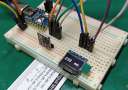
PID温度控制器测试 为了测试电路,使用了以下设置,Meco 450B+万用表显示Arduino引脚11的输出PWM信号的占空比。我使用了包含12V加热元件的3D打印机作为加热器,同时使用5V电源为Arduino供电。

现在,要设置温度,您需要按下旋转编码器的按钮,该按钮设置了设定值或PID算法的目标温度,再次按下按钮使更改生效,加热器块开始加热,您可以看到占空比也增加了,我将温度设置为64℃。

一旦达到所需温度,PWM占空比就会降低,当控制器想要补偿误差并提高温度时,您可以观察到占空比中的某个尖峰。

以上就是本文的全部内容,希望您喜欢这篇文章并学到了一些新东西。如果您对文章有任何疑问,可以随时在本帖下面进行回复。 |