|
Espressif ESP32设备无处不在:它们价格便宜,易于使用,并且Espressif IDF环境和构建系统实际上非常好,并且对包括Eclipse在内的我来说都运行良好。对ESP32进行编程的默认方法是:a)按下某些按钮进入UART引导加载程序,以及b)使用USB电缆用ESP-IDF烧写应用程序。
如果ESP32直接连接到主机PC,则可以正常工作。但就我而言,它位于NXP Kinetis K22FX512 ARM Cortex-M4F微控制器的后面,并且不能由主机PC直接访问。因此,我必须找到一种方法来允许通过ARM Cortex-M引导加载ESP32,这是本文的主题。

TTGO ESP32 MICRO-D4模块
ESP32模组 我选择TTGO TTGO Micro-32模块是因为它价格便宜,可用的教程和文档很多,并且比通常的ESP32小得多。
下面比较一下“常规” ESP32模块和带有ESP32 PICO-D4的Micro-32:

带有常规ESP32模块的TTGO Micro-32
上述开发板的左侧包括UART-2-USB CDC接口,用于对设备进行编程。有两个按钮:EN /复位(低电平有效)和启动选择开关(IO0)。
在GitHub上可用的模块引脚下方:

TTGO ESP32
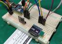
首先,将模块焊接在插针插座上,然后与面包板一起使用:

TTGO ESP32扩展板
要使用该模块,只需要几个引脚即可: ● GND和3.3V ● EN,它是一个复位(低电平有效) ● IO0(低有效),用于在复位期间将模块置于串行引导加载程序模式 ● UART Tx和Rx用于串行连接和串行引导程序 下一步是在机器人顶部构建第一个原型板作为基础板:

V1.0原理图

带有TTGO Shield V1.0的机器人
由于机器人的3.3V DC-DC转换器无法在所有模式下提供所需的mA,因此添加了一个额外的5V DC-DC转换器。该版本中缺少的其他东西是GND和EN信号之间为100 nF。
编程模块 机器人上的主处理器是NXP K22FX512。已使用基于Eclipse的MCUXpresso IDE和MCUXpresso SDK开发了该软件。

sumo项目
想法是,K22充当主机PC和ESP32之间的网关。

连接图
要进入ESP的自举程序模式,在释放复位信号时,IO0信号需要保持低电平。典型的ESP32板带有UART-2-USB转换器,并且使用带有流控制信号的USB CDC来完成EN和IO0的切换。因此,基本上,在K22上,我必须运行USB CDC堆栈并正确处理流控制信号。
机械手上的命令行外壳可直接访问ESP32模块:

ESP32 shell命令
USB CDC 恩智浦MCUXpresso SDK中有一个基本的USB CDC示例项目。但这仅适用于非常简单的情况,不能重入。这个问题并不是那么容易找到:基本上使用启用了流控制的终端,USB堆栈没有发回ACK包,从而导致主机上的终端阻塞。使用LeCroy USB分析仪来发现问题非常有帮助:

LeCroy USB协议分析仪
要更改的第一件事是对virtual_com.c中的接收数据使用可重入环形缓冲区,并计划下一个接收事件。所做的更改在下面用“ << EST”标记。 - case kUSB_DeviceCdcEventRecvResponse:
- {
- if ((1 == s_cdcVcom.attach) && (1 == s_cdcVcom.startTransactions))
- {
- #if 1 /* << EST */ size_t i, dataSize; dataSize = epCbParam->length;
- if (dataSize!=0 && dataSize!=(size_t)-1) {
- i = 0;
- while(i<dataSize) { McuRB_Put(usb_rxBuf, &s_currRecvBuf[i]); i++; } } #endif #if defined(FSL_FEATURE_USB_KHCI_KEEP_ALIVE_ENABLED) && (FSL_FEATURE_USB_KHCI_KEEP_ALIVE_ENABLED > 0U) && \
- defined(USB_DEVICE_CONFIG_KEEP_ALIVE_MODE) && (USB_DEVICE_CONFIG_KEEP_ALIVE_MODE > 0U) && \
- defined(FSL_FEATURE_USB_KHCI_USB_RAM) && (FSL_FEATURE_USB_KHCI_USB_RAM > 0U)
- s_waitForDataReceive = 0;
- USB0->INTEN |= USB_INTEN_SOFTOKEN_MASK;
- #endif
- //if (!s_recvSize) /* << EST */ { /* Schedule buffer for next receive event */ error = USB_DeviceCdcAcmRecv(handle, USB_CDC_VCOM_BULK_OUT_ENDPOINT, s_currRecvBuf, g_UsbDeviceCdcVcomDicEndpoints[0].maxPacketSize); #if defined(FSL_FEATURE_USB_KHCI_KEEP_ALIVE_ENABLED) && (FSL_FEATURE_USB_KHCI_KEEP_ALIVE_ENABLED > 0U) && \
- defined(USB_DEVICE_CONFIG_KEEP_ALIVE_MODE) && (USB_DEVICE_CONFIG_KEEP_ALIVE_MODE > 0U) && \
- defined(FSL_FEATURE_USB_KHCI_USB_RAM) && (FSL_FEATURE_USB_KHCI_USB_RAM > 0U)
- s_waitForDataReceive = 1;
- USB0->INTEN &= ~USB_INTEN_SOFTOKEN_MASK;
- #endif
- }
- }
- }
- break;
接下来的事情是正确处理kUSB_DeviceCdcEventSetControlLineState并调用应用程序回调: - case kUSB_DeviceCdcEventSetControlLineState:
- {
- s_usbCdcAcmInfo.dteStatus = acmReqParam->setupValue;
- /* activate/deactivate Tx carrier */
- if (acmInfo->dteStatus & USB_DEVICE_CDC_CONTROL_SIG_BITMAP_CARRIER_ACTIVATION)
- {
- acmInfo->uartState |= USB_DEVICE_CDC_UART_STATE_TX_CARRIER;
- }
- else
- {
- acmInfo->uartState &= (uint16_t)~USB_DEVICE_CDC_UART_STATE_TX_CARRIER;
- }
-
- /* activate carrier and DTE. Com port of terminal tool running on PC is open now */
- if (acmInfo->dteStatus & USB_DEVICE_CDC_CONTROL_SIG_BITMAP_DTE_PRESENCE)
- {
- acmInfo->uartState |= USB_DEVICE_CDC_UART_STATE_RX_CARRIER;
- }
- /* Com port of terminal tool running on PC is closed now */
- else
- {
- acmInfo->uartState &= (uint16_t)~USB_DEVICE_CDC_UART_STATE_RX_CARRIER;
- }
- /* Indicates to DCE if DTE is present or not */
- acmInfo->dtePresent = (acmInfo->dteStatus & USB_DEVICE_CDC_CONTROL_SIG_BITMAP_DTE_PRESENCE) ? true : false;
- #if 1 /* << EST */ // http://markdingst.blogspot.com/2014/06/implementing-usb-communication-device.html // bit 0: Indicates to DCE if DTE is present or not. This signal corresponds to V.24 signal 108/2 and RS232 signal DTR. // 0: DTE is not present. // 1: DTE is present // bit 1: Carrier control for half duplex modems. This signal corresponds to V.24 signal 105 and RS232 signal RTS. // 0: Deactivate carrier. // 1: Activate carrier. // The device ignores the value of this bit when operating in full duplex mode. McuESP32_UartState_Callback(acmInfo->uartState);
- #if ENABLED_USB_CDC_LOGGING
- McuRTT_printf(0, "CDC: set control dteStatus: %d, uartState: %d, dtePresent: %d, attach: %d, startTransaction: %d\r\n", s_usbCdcAcmInfo.dteStatus, acmInfo->uartState, acmInfo->dtePresent, s_cdcVcom.attach, s_cdcVcom.startTransactions);
- #endif
- #endif
-
- /* Initialize the serial state buffer */
- acmInfo->serialStateBuf[0] = NOTIF_REQUEST_TYPE; /* bmRequestType */
- acmInfo->serialStateBuf[1] = USB_DEVICE_CDC_NOTIF_SERIAL_STATE; /* bNotification */
- acmInfo->serialStateBuf[2] = 0x00; /* wValue */
- acmInfo->serialStateBuf[3] = 0x00;
- acmInfo->serialStateBuf[4] = 0x00; /* wIndex */
- acmInfo->serialStateBuf[5] = 0x00;
- acmInfo->serialStateBuf[6] = UART_BITMAP_SIZE; /* wLength */
- acmInfo->serialStateBuf[7] = 0x00;
- /* Notify to host the line state */
- acmInfo->serialStateBuf[4] = acmReqParam->interfaceIndex;
- /* Lower byte of UART BITMAP */
- uartBitmap = (uint8_t *)&acmInfo->serialStateBuf[NOTIF_PACKET_SIZE + UART_BITMAP_SIZE - 2];
- uartBitmap[0] = acmInfo->uartState & 0xFFu;
- uartBitmap[1] = (acmInfo->uartState >> 8) & 0xFFu;
- len = (uint32_t)(NOTIF_PACKET_SIZE + UART_BITMAP_SIZE);
- if (0 == ((usb_device_cdc_acm_struct_t *)handle)->hasSentState)
- {
- error = USB_DeviceCdcAcmSend(handle, USB_CDC_VCOM_INTERRUPT_IN_ENDPOINT, acmInfo->serialStateBuf, len);
- if (kStatus_USB_Success != error)
- {
- usb_echo("kUSB_DeviceCdcEventSetControlLineState error!");
- }
- ((usb_device_cdc_acm_struct_t *)handle)->hasSentState = 1;
- }
-
- /* Update status */
- if (acmInfo->dteStatus & USB_DEVICE_CDC_CONTROL_SIG_BITMAP_CARRIER_ACTIVATION)
- {
- /* To do: CARRIER_ACTIVATED */
- #if ENABLED_USB_CDC_LOGGING
- McuRTT_printf(0, "CARRIER_ACTIVATED\r\n");
- #endif
- }
- else
- {
- /* To do: CARRIER_DEACTIVATED */
- #if ENABLED_USB_CDC_LOGGING
- McuRTT_printf(0, "CARRIER_DEACTIVATED\r\n");
- #endif
- }
- #if 0
- if (acmInfo->dteStatus & USB_DEVICE_CDC_CONTROL_SIG_BITMAP_DTE_PRESENCE)
- #else /* << EST */ if ( (acmInfo->dteStatus & USB_DEVICE_CDC_CONTROL_SIG_BITMAP_DTE_PRESENCE)
- || (s_cdcVcom.attach && (acmInfo->dteStatus==USB_DEVICE_CDC_CONTROL_SIG_BITMAP_CARRIER_ACTIVATION) /* && !s_cdcVcom.startTransactions*/) /* << EST */ ) #endif { /* DTE_ACTIVATED */ if (1 == s_cdcVcom.attach) { s_cdcVcom.startTransactions = 1; #if ENABLED_USB_CDC_LOGGING McuRTT_printf(0, "startTransactions=1\r\n"); #endif #if defined(FSL_FEATURE_USB_KHCI_KEEP_ALIVE_ENABLED) && (FSL_FEATURE_USB_KHCI_KEEP_ALIVE_ENABLED > 0U) && \
- defined(USB_DEVICE_CONFIG_KEEP_ALIVE_MODE) && (USB_DEVICE_CONFIG_KEEP_ALIVE_MODE > 0U) && \
- defined(FSL_FEATURE_USB_KHCI_USB_RAM) && (FSL_FEATURE_USB_KHCI_USB_RAM > 0U)
- s_waitForDataReceive = 1;
- USB0->INTEN &= ~USB_INTEN_SOFTOKEN_MASK;
- s_comOpen = 1;
- usb_echo("USB_APP_CDC_DTE_ACTIVATED\r\n");
- #endif
- }
- }
- else
- {
- /* DTE_DEACTIVATED */
- if (1 == s_cdcVcom.attach)
- {
- // s_cdcVcom.startTransactions = 0;
- #if ENABLED_USB_CDC_LOGGING
- McuRTT_printf(0, "startTransactions=0\r\n");
- #endif
- }
- }
- }
- break;
辅助程序处理GPIO引脚切换: - static void AssertReset(void) {
- McuGPIO_SetAsOutput(McuESP32_RF_EN_Pin, false); /* output, LOW */
- }
-
- static void DeassertReset(void) {
- McuGPIO_SetAsInput(McuESP32_RF_EN_Pin);
- }
-
- static void DoReset(void) {
- AssertReset();
- vTaskDelay(pdMS_TO_TICKS(1));
- DeassertReset();
- }
-
- static void AssertBootloaderMode(void) {
- McuGPIO_SetAsOutput(McuESP32_RF_IO0_Pin, false); /* output, LOW */
- }
-
- static void DeassertBootloaderMode(void) {
- McuGPIO_SetAsInput(McuESP32_RF_IO0_Pin);
- }
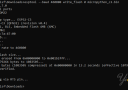
现在介绍控制状态序列。 我已经使用不同的终端程序以及在连接,编程和最后复位期间ESP-IDF如何使用DTR / RTS信号验证了它: - /* idf.py flash sequence:
- *
- * 00> State: 3, DtrRts: 3
-
- * 00> State: 2, DtrRts: 1
- * 00> State: 3, DtrRts: 3
- * 00> State: 1, DtrRts: 2
- * 00> State: 0, DtrRts: 0
-
- * 00> State: 2, DtrRts: 1
- * 00> State: 3, DtrRts: 3
- * 00> State: 1, DtrRts: 2
- * 00> State: 0, DtrRts: 0
- *
- * reset at the end:
- * 00> State: 2, DtrRts: 1
- * 00> State: 0, DtrRts: 0
- */
“魔术”是在回调本身中完成的:它会记住控制线信号的先前状态,并自动切换到编程模式并返回正常模式: - void McuESP32_UartState_Callback(uint8_t state) { /* callback for DTR and RTS lines */
- static uint8_t prevState = -1;
- static uint8_t prevPrevState = -1;
- uint8_t DtrRts;
-
- #if McuESP32_VERBOSE_CONTROL_SIGNALS
- McuRTT_printf(0, "state: %d, prev: %d, prevprev: %d\r\n", state, prevState, prevPrevState);
- #endif
- if (state != prevState) {
- if (McuESP32_UsbPrgMode==McuESP32_USB_PRG_MODE_AUTO || McuESP32_UsbPrgMode==McuESP32_USB_PRG_MODE_ON) {
- /*
- * DTR RTS EN GPIO0
- * 1 1 1 1
- * 0 0 1 1
- * 1 0 0 0
- * 0 1 1 0
- */
- DtrRts = 0;
- if ((state&1)==1) { /* DTR */
- DtrRts |= 2; /* DTR set */
- }
- if ((state&2)==2) { /* DTR */
- DtrRts |= 1; /* RTS set */
- }
- #if McuESP32_VERBOSE_CONTROL_SIGNALS
- McuRTT_printf(0, "State: %d, DtrRts: %d\r\n", state, DtrRts);
- #endif
- switch(DtrRts) {
- default:
- case 0:
- DeassertReset();
- McuWait_Waitus(100); /* block for a short time (in the ISR!!!) ==> should have a 100 uF added to the reset line */
- DeassertBootloaderMode();
- //McuRTT_printf(0, "Release both: %d\r\n", DtrRts);
- break;
- case 1:
- AssertBootloaderMode();
- //McuRTT_printf(0, "assert BL: %d\r\n", DtrRts);
- break;
- case 2:
- if (McuGPIO_IsLow(McuESP32_RF_EN_Pin)) {
- if (McuGPIO_IsLow(McuESP32_RF_IO0_Pin)) {
- McuESP32_IsProgramming = true; /* the DeassertReset() below will enter bootloader mode */
- McuRTT_printf(0, "Enter Bootloader Mode\r\n");
- } else {
- McuESP32_IsProgramming = false; /* the DeassertReset() below will do a reset without bootloader */
- McuRTT_printf(0, "Reset\r\n");
- }
- }
- DeassertReset();
- McuWait_Waitus(100); /* block for a short time (in the ISR!!!) ==> should have a 100 uF added to the reset line */
- //McuRTT_printf(0, "release reset: %d\r\n", DtrRts);
- break;
- case 3:
- AssertReset();
- //McuRTT_printf(0, "assert reset: %d\r\n", DtrRts);
- break;
- } /* switch */
- if (state==0 && prevState==2 && prevPrevState==0) {
- // reset sequence with idf.py and Arduino IDE:
- // State: 0 DtrRts: 0 Release both: 0
- // State: 2 DtrRts: 1 assert BL: 1
- // State: 0 DtrRts: 0 Release both: 0
- McuRTT_printf(0, "Request Reset\r\n");
- McuESP32_ScheduleReset = true; /* cannot do reset sequence here, as called from an interrupt, so we cannot block */
- McuESP32_IsProgramming = false;
- }
- }
- prevPrevState = prevState;
- prevState = state;
- } /* if state!=prevState */
- }
UART任务 ESP32的Tx和Rx由K22上的两个简单FreeRTOS任务处理。 以下是在接收方的代码: - static void UartRxTask(void *pv) { /* task handling characters sent by the ESP32 module */
- unsigned char ch;
- BaseType_t res;
-
- for(;;) {
- res = xQueueReceive(uartRxQueue, &ch, portMAX_DELAY);
- if (res==pdPASS) {
- #if PL_CONFIG_USE_USB_CDC_ESP32
- if (McuESP32_IsProgramming && USB_CdcIsConnected()) { /* send directly to programmer attached on the USB */
- USB_CdcStdio.stdOut(ch); /* forward to USB CDC and the programmer on the host */
- }
- if (McuESP32_CopyUartToShell && !McuESP32_IsProgramming) { /* only write to shell if not in programming mode. Programming mode might crash RTT */
- SHELL_SendChar(ch); /* write on console output */
- }
- #else
- SHELL_SendChar(ch); /* write on console output */
- #endif
- }
- }
- }
以下是发送的任务代码: - static void UartTxTask(void *pv) { /* task handling sending data to the ESP32 module */
- unsigned char ch;
- BaseType_t res;
- bool workToDo;
-
- for(;;) {
- if (McuESP32_ScheduleReset) {
- McuESP32_ScheduleReset = false;
- McuRTT_printf(0, "Performing reset\r\n");
- DoReset();
- }
- workToDo = false;
- do {
- res = xQueueReceive(uartTxQueue, &ch, 0); /* poll queue */
- if (res==pdPASS) {
- workToDo = true;
- McuESP32_CONFIG_UART_WRITE_BLOCKING(McuESP32_CONFIG_UART_DEVICE, &ch, 1);
- }
- } while (res==pdPASS);
- #if PL_CONFIG_USE_USB_CDC_ESP32
- while (USB_CdcStdio.keyPressed()) {
- workToDo = true;
- USB_CdcStdio.stdIn(&ch); /* read byte */
- McuESP32_CONFIG_UART_WRITE_BLOCKING(McuESP32_CONFIG_UART_DEVICE, &ch, 1); /* send to the module */
- if (McuESP32_CopyUartToShell && !McuESP32_IsProgramming) {
- SHELL_SendChar(ch); /* copy to console */
- }
- }
- #endif
- if (!workToDo) {
- vTaskDelay(pdMS_TO_TICKS(5));
- }
- }
- }
这样,我可以连接到NXPK22的USB端口,并使用Eclipse编程ESP32:

使用Eclipse编程ESP32
总结 可以将NXP Kinetis K22用作ESP32模块的网关:可以对其进行编程,也可以用于串行/ UART /终端连接。 还未进行优化,因此编程速度目前限制为115200波特率。 由于idf.py正在压缩图像,因此编程速度约为150 kBits / s。 |