风筝
发表于: 2022-4-1 18:08:53 | 显示全部楼层

在本篇文章中,我们将介绍如何在UART和I2C模式下将Atlas Scientific公司的PH传感器与Arduino UNO开发板进行连接。 Atlas Scientific的EZO Ph电路板使工程师能够以与传统上仅在昂贵的台式仪表中才能找到的相同精度和功能读取pH值。Atlast Ph传感器套件随附了Ph探头、EZO电路板、信号连接器板、校准解决方案和缓冲存储解决方案。


在以前的帖子中,我对两种不同类型的Ph传感器进行了详细介绍,一种是DfRobot公司的Ph传感器,另一种是Graylogix Ph传感器。与这些模拟Ph传感器相比,Atlas Scientific的Ph传感器是最科学和准确的Ph传感器之一。它同时具有UART和I2C接口。


在这篇文章中,我们将介绍有关Atlas Scientific Ph传感器套件的以下内容。

●    Ph电极和信号连接器板的基本介绍和详细信息

●    了解EZO Ph电路板

●    检查放置Ph电极的缓冲溶液

●    了解用于Ph传感器校准的不同解决方案

●    在UART和I2C模式下将Atlas Ph传感器与Arduino连接

●    了解从UART接口切换到I2C接口或Vice-Versa的方法

●    使用Ph校准溶液的Ph传感器校准方法

●    使用EZO I2C Ph库

●    使用OLED显示屏设计便携式pH计

●    使用水、牛奶或任何标准溶液等液体测试传感器性能


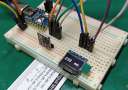
所需的组件

●    Arduino Nano开发板

●    Atlas Scientific Ph传感器套件

●    0.96寸I2C OLED显示屏

●    连接跳线

●    面包板


Atlas Scientific Ph传感器套件

现在让我们熟悉一下Ph传感器套件。 Atlas Scientific Ph传感器套件是用于液体pH测量的工业级Ph传感器。这是目前市场上最好的Ph传感器。

Atlas-Scientific-Ph-Sensor-Kit.jpg

完整的套件包含:

1.    双结银/氯化银实验室级pH探头

2.    电气隔离EZO载板

3.    EZO pH电路板

4.    125 ml 校准溶液(pH 4、pH 7 和 pH 10)

5.    125 ml pH 储存液


1.   Atlas Ph探头

这是一个末端带有镀金BNC连接器的Ph传感器探头。这款pH探头采用优质结构和坚固的环氧树脂设计,适合在实验室和现场环境中重复使用。

Atlas-Ph-Probe.jpg


传感器带有一个保存在缓冲溶液中的末端。要使用此传感器,您必须取下装满缓冲溶液的浸泡瓶。当您取下盖子时,您可以看到电极。该灯泡可以处理低离子和超纯水读数,包括高pH溶液以及含有重金属的样品。

tip.jpg


该电极基于电位pH测量原理。该探头的结构图如下所示。它是用银线和氯化银溶液制成的。使用该组合以电压方式读取Ph值。

Ph-Electrode-Construction.jpg


pH探头是双接界银/氯化银pH探针头类型。测量范围在0 - 14之间,最大分辨率为+/- 0.001。探头可承受100 PSI的最大压力并工作在-5 至 99°C 的温度范围内。


不使用传感器时,将传感器浸入缓冲溶液中。不要让这个电极暴露在空气中。浸泡瓶用于防止灯泡变干。


2.   电隔离EZO载板

电隔离EZO载板是将Atlas Scientific电路板连接到控制器的有效方式。它消除了对面包板和外部隔离器的需求。该载板采用最新的隔离技术,使我们能够将隔离放入更小尺寸的电路中。顶部的五个引脚保持打开状态,供您决定如何将其连接到您的系统。

Electrically-Isolated-EZO-Carrier-Board.jpg


它可以接受UART或I2C接口形式的输入数据。它工作在3.0V - 5.0V之间,典型电流消耗为5v 时 28mA 和 3.3V 时 22mA。在省电或睡眠模式下,电流消耗为 2.6mA。


3.   EZO pH 电路板

该板也是信号连接板的一部分。它被称为EZO Ph电路板。 EZO pH电路板可与任何现成的pH探头、传感器和电极配合使用。该设备从pH探头、传感器和电极读取pH值。这与环氧树脂的所有侧面绝缘。

EZO-pH-Circuit.jpg


该板具有指示通信协议类型的LED。 EZO电路板可以直接安装在隔离载板上。 Ph探头还需要使用BNC连接器连接到信号载板。

EZO-Carrier.jpg


以下是与 EZO Ph 电路板相关的功能规格和数据协议。

●    从 0.001 到 14.000 的全范围 pH 读数

●    精确到千分之一的 pH 读数 (+/- 0.02)

●    与温度相关或与温度无关的读数

●    灵活的校准协议支持单点、2 点或 3 点校准

●    使用 Atlas Scientific pH 探头每年只需校准一次

●    单次读取或连续读取模式

●    数据格式为ASCII

●    UART 异步串行连接(RX/TX 电压摆幅 0-VCC)

●    I2C(默认 I2C 地址 0x63)

●    兼容任何支持 UART 或 I2C 协议的微处理器

●    工作电压:3.3V 至 5V

●    适用于任何现成的 pH 探头

●    睡眠模式功耗 0.995mA at 3.3V


4.   校准溶液(pH 4、pH 7 和 pH 10)

我们还通过Ph传感器校准解决方案得到标准溶液包。这包含两袋校准溶液,每袋的pH值分别为 Ph 4、Ph 7 和 Ph 10。

calibration-solutions-pH-4-pH-7-pH-10.jpg


在袋子的背面,有使用该解决方案的说明。


5.   pH储存缓冲液

这是通常称为缓冲溶液的存储溶液。该解决方案用于存放Ph传感器探头并防止灯泡在不使用时变干。

pH-storage-Buffer-solution.jpg

跳转到指定楼层
回复

使用道具 举报

风筝
发表于: 2022-4-2 09:40:37 | 显示全部楼层

Atlas Ph传感器与Arduino开发板的连接方式

让我们将Atlas Scientific的Ph传感器与Arduino UNO开发板连接起来。可以在UART模式或I2C模式下连接该传感器。


但问题是如何识别传感器是处于UART模式还是I2C模式。所以EZO Ph电路板上有一个颜色指示LED灯。如果LED颜色为绿色或蓝绿色,则处于UART模式。如果LED颜色为蓝色,则传感器将处于I2C模式。

UART-I2C-Mode.jpg


UART模式连接

您可以使用以下连接方式以UART模式将Atlas Ph传感器与Arduino进行连接。

ATlas-Ph-Sensor-Arduino-UART.jpg


将传感器的VCC和GND分别连接到Arduino的3.3V和GND引脚。 Ph传感器板的UART引脚,即Tx和Rx,可以连接到任何支持软件串口的引脚。本文中将传感器的Tx和Rx分别连接到Arduino的数字引脚3和2。

Arduino-Ph-Sensor-UART-Connection.jpg


I2C模式连接

您可以使用以下连接在I2C模式下将Atlas Ph传感器与Arduino进行连接。

ATlas-Ph-Sensor-Arduino-I2C.jpg


将传感器的VCC和GND分别连接到Arduino的3.3V和GND引脚。将传感器的SDA和SCL引脚分别连接到Arduino的A4和A5引脚。

Arduino-Ph-Sensor-I2C-Connection.jpg


测试UART模式的代码和从UART到I2C模式的切换

如果LED颜色为绿色或蓝绿色,则电路板处于UART模式。默认情况下,传感器处于UART模式。将传感器的Tx和Rx引脚连接到Arduino的引脚2和引脚3,并将电源引脚连接到3.3V。


以下是UART模式通信的Atlas Ph传感器Arduino代码。

  1. #include <SoftwareSerial.h>                           //we have to include the SoftwareSerial library, or else we can't use it
  2. #define rx 2                                          //define what pin rx is going to be
  3. #define tx 3                                          //define what pin tx is going to be

  4. SoftwareSerial myserial(rx, tx);                      //define how the soft serial port is going to work

  5. String inputstring = "";                              //a string to hold incoming data from the PC
  6. String sensorstring = "";                             //a string to hold the data from the Atlas Scientific product
  7. boolean input_string_complete = false;                //have we received all the data from the PC
  8. boolean sensor_string_complete = false;               //have we received all the data from the Atlas Scientific product
  9. float pH;                                             //used to hold a floating-point number that is the pH


  10. void setup()
  11. {
  12.   Serial.begin(9600);                                 //set baud rate for the hardware serial port_0 to 9600
  13.   myserial.begin(9600);                               //set baud rate for the software serial port to 9600
  14.   inputstring.reserve(10);                            //set aside some bytes for receiving data from the PC
  15.   sensorstring.reserve(30);                           //set aside some bytes for receiving data from Atlas Scientific product
  16. }

  17. void serialEvent()
  18. {
  19.   inputstring = Serial.readStringUntil(13);           //read the string until we see a <CR>
  20.   input_string_complete = true;                       //set the flag used to tell if we have received a completed string from the PC
  21. }


  22. void loop()
  23. {
  24.   if (input_string_complete == true)                  //if a string from the PC has been received in its entirety
  25.   {
  26.     myserial.print(inputstring);                      //send that string to the Atlas Scientific product
  27.     myserial.print('\r');                             //add a <CR> to the end of the string
  28.     inputstring = "";                                 //clear the string
  29.     input_string_complete = false;                    //reset the flag used to tell if we have received a completed string from the PC
  30.   }

  31.   if (myserial.available() > 0)                       //if we see that the Atlas Scientific product has sent a character
  32.   {
  33.     char inchar = (char)myserial.read();              //get the char we just received
  34.     sensorstring += inchar;                           //add the char to the var called sensorstring
  35.     if (inchar == '\r')                               //if the incoming character is a <CR>
  36.     {
  37.       sensor_string_complete = true;                  //set the flag
  38.     }
  39.   }

  40.   if (sensor_string_complete == true)                 //if a string from the Atlas Scientific product has been received in its entirety
  41.   {
  42.     Serial.println(sensorstring);                     //send that string to the PC's serial monitor
  43.     sensorstring = "";                                //clear the string
  44.     sensor_string_complete = false;                   //reset the flag used to tell if we have received a completed string from the Atlas Scientific product
  45.   }
  46. }
复制代码

从工具菜单中,选择Arduino UNO开发板以及对应的COM端口。 然后点击上传按钮上传代码。


上传代码后,打开串口监视器,选择波特率9600并启用回车选项。 串口监视器将开始显示Ph值。


输入I并单击发送。 然后将出现一条OK消息。

UART-TO-i2c.jpg


传感器的默认I2C地址为99(0x63)。 如果要更改为I2C模式,输入“I2C,99”或介于0到127之间的任何值。然后单击发送。 现在传感器更改为I2C模式,LED颜色将变为蓝色。


测试I2C代码和从I2C到UART模式的切换

如 LED灯的颜色为蓝色,则Ph传感器处于I2C模式。 因此,移除Tx、Rx线,然后将传感器的SDA和SCL引脚连接到Arduino开发板的A4和A5。


以下是用于I2C通信的Atlas Ph传感器的Arduino代码。

  1. #include <Wire.h>                //enable I2C.
  2. #define address 99               //default I2C ID number for EZO pH Circuit is 99


  3. char computerdata[20];           //we make a 20 byte character array to hold incoming data from a pc/mac/other.
  4. byte received_from_computer = 0; //we need to know how many characters have been received.
  5. byte serial_event = 0;           //a flag to signal when data has been received from the pc/mac/other.
  6. byte code = 0;                   //used to hold the I2C response code.
  7. char ph_data[20];                //we make a 20 byte character array to hold incoming data from the pH circuit.
  8. byte in_char = 0;                //used as a 1 byte buffer to store inbound bytes from the pH Circuit.
  9. byte i = 0;                      //counter used for ph_data array.
  10. int time_ = 815;                 //used to change the delay needed depending on the command sent to the EZO Class pH Circuit.
  11. float ph_float;                  //float var used to hold the float value of the pH.


  12. void setup()                     //hardware initialization.
  13. {
  14.   Serial.begin(9600);           //enable serial port.
  15.   Wire.begin();                 //enable I2C port.
  16. }


  17. void serialEvent() {                                                              //this interrupt will trigger when the data coming from the serial monitor(pc/mac/other) is received.
  18.   received_from_computer = Serial.readBytesUntil(13, computerdata, 20);           //we read the data sent from the serial monitor(pc/mac/other) until we see a <CR>. We also count how many characters have been received.
  19.   computerdata[received_from_computer] = 0;                                       //stop the buffer from transmitting leftovers or garbage.
  20.   serial_event = true;                                                            //set the serial event flag.
  21. }


  22. void loop() {                                                                     //the main loop.
  23.   if (serial_event == true) {                                                     //if a command was sent to the EZO device.
  24.     for (i = 0; i <= received_from_computer; i++) {                               //set all char to lower case, this is just so this exact sample code can recognize the "sleep" command.
  25.       computerdata[i] = tolower(computerdata[i]);                                 //"Sleep" ≠ "sleep"
  26.     }
  27.     i=0;                                                                          //reset i, we will need it later
  28.     if (computerdata[0] == 'c' || computerdata[0] == 'r')time_ = 815;             //if a command has been sent to calibrate or take a reading we wait 815ms so that the circuit has time to take the reading.
  29.     else time_ = 250;                                                             //if any other command has been sent we wait only 250ms.
  30.    

  31.     Wire.beginTransmission(address);                                              //call the circuit by its ID number.
  32.     Wire.write(computerdata);                                                     //transmit the command that was sent through the serial port.
  33.     Wire.endTransmission();                                                       //end the I2C data transmission.


  34.     if (strcmp(computerdata, "sleep") != 0) {                                      //if the command that has been sent is NOT the sleep command, wait the correct amount of time and request data.
  35.                                                                                   //if it is the sleep command, we do nothing. Issuing a sleep command and then requesting data will wake the circuit.

  36.       delay(time_);                                                               //wait the correct amount of time for the circuit to complete its instruction.

  37.       Wire.requestFrom(address, 20, 1);                                           //call the circuit and request 20 bytes (this may be more than we need)
  38.       code = Wire.read();                                                         //the first byte is the response code, we read this separately.

  39.       switch (code) {                       //switch case based on what the response code is.
  40.         case 1:                             //decimal 1.
  41.           Serial.println("Success");        //means the command was successful.
  42.           break;                            //exits the switch case.

  43.         case 2:                             //decimal 2.
  44.           Serial.println("Failed");         //means the command has failed.
  45.           break;                            //exits the switch case.

  46.         case 254:                           //decimal 254.
  47.           Serial.println("Pending");        //means the command has not yet been finished calculating.
  48.           break;                            //exits the switch case.

  49.         case 255:                           //decimal 255.
  50.           Serial.println("No Data");        //means there is no further data to send.
  51.           break;                            //exits the switch case.
  52.       }


  53.       while (Wire.available()) {            //are there bytes to receive.
  54.         in_char = Wire.read();              //receive a byte.
  55.         ph_data[i] = in_char;               //load this byte into our array.
  56.         i += 1;                             //incur the counter for the array element.
  57.         if (in_char == 0) {                 //if we see that we have been sent a null command.
  58.           i = 0;                            //reset the counter i to 0.
  59.           break;                            //exit the while loop.
  60.         }
  61.       }

  62.       Serial.println(ph_data);              //print the data.
  63.     }
  64.     serial_event = false;                   //reset the serial event flag.
  65.   }
  66.   //Uncomment this section if you want to take the pH value and convert it into floating point number.
  67.   //ph_float=atof(ph_data);
  68. }
复制代码

选择开发板型号和COM端口并上传代码。


上传代码后,再次打开串口监视器。 监视器将显示对应的pH值显示内容。如果需要将传感器模式从I2C更改为UART,请键入I并发送。 然后会再次出现成功消息。 现在输入“baud,9600”并点击发送按钮。 LED颜色将立即再次变为绿色。

i2c-TO-uart.jpg


使用EZO I2C库

在本章节我们将使用EZO I2C库来获得Ph传感器的稳定读数。


EZO I2C库的GitHub存储库包含大量示例代码。 如果您正在开发一些系统,您可以参考这些代码。 本文将只使用这个库来读取I2C模式下的传感器值。

EZO I2C library

EZO I2C library


启用传感器的I2C模式并正确接线。 复制以下代码并粘贴到Arduino IDE。

main.rar (1.1 KB, 下载次数: 3)


现在您可以将代码上传到Arduino开发板。上传完成后,打开串口监视器。 传感器将给出正确的pH读数。

I2C-ezo-OUTPUT.jpg

回复

使用道具 举报

风筝
发表于: 2022-4-2 10:42:02 | 显示全部楼层

Atlas Ph传感器校准

让我们看看如何校准Atlas Ph传感器。传感器套件随附3袋pH溶液。将此溶液放入3个不同的玻璃杯中。红色的是ph 4,黄色是ph 7,蓝色是ph 10。

Ph-Calibration-Solution.jpg


根据UART模式的连接方式组装Arduino和Ph 传感器电路,并上传UART代码。我们将使用UART代码进行校准。上传UART代码完成后,打开串口监视器。


Ph传感器放置在缓冲溶液中。取下传感器盖并用水冲洗。

Atlas-Ph-Sensor-Calibration.jpg


等待传感器读数稳定。读数可能需要5-10分钟才能获得稳定的读数。现在,只要读数稳定,您就可以开始校准过程。

Atlas-Ph-Sensor-Calibration-Arduino.jpg


现在将Ph探头放入ph 4溶液,然后输入以下命令。

  1. cal,4,low
复制代码

然后点击发送按钮。传感器将针对ph值4进行校准。

low.jpg


现在从ph 4溶液中取出传感器并用水冲洗。然后将其放入ph 7溶液中。然后输入以下命令。

  1. cal,7,mid
复制代码

点击发送按钮,传感器针对ph值7进行了校准。

mid.jpg


用Ph 10溶液再次重复此操作。取出传感器用水冲洗并放入ph 10溶液中。在对话框中,输入以下命令。

  1. cal,10,high
复制代码

点击发送按钮,传感器校准为 ph 值 10。

high.jpg


以上就是基于Arduino开发板使用Atlas Ph传感器的方法。如果有任何疑问,请随时在本帖下面进行回复。

回复

使用道具 举报

您需要登录后才可以回帖 登录 | 立即注册

本版积分规则

主题 700 | 回复: 1480


手机版|

GMT+8, 2024-4-20 09:18 , Processed in 0.316624 second(s), 6 queries , Gzip On, MemCache On. Powered by Discuz! X3.5

YiBoard一板网 © 2015-2022 地址:河北省石家庄市长安区高营大街 ( 冀ICP备18020117号 )

快速回复 返回顶部 返回列表