|
如今,在通信和物联网项目中,建立无线连接和创建无线网络非常重要。在本篇文章中,您将学习如何在两个Arduino开发板之间建立无线连接并使用NRF24L01模块创建无线网络。
什么是NRF24L01模块及其工作原理? 无线通信有多种方式,如蓝牙、WiFi等。使用NRF24L01模块是最实惠、最简单、最实用的方法之一。
NRF24L01模块是一个收发器模块,这意味着它可以发送和接收数据。 NRF24L01工作在2.4 GHz频率并使用GFSK调制。该模块的最大数据传输速度高达2Mbps,最大传输距离为空旷处100米(对于带外部天线的型号,距离可以为1 km)。 参数 | 典型值 | 工作电压 | 3.3 v | 发送模式下的使用电流 | 11.3 mA | 接收模式下的使用电流 | 12.3 mA | 睡眠模式下的使用电流 | 900 nA | 温度范围 | -40至+85 C | 价格 | 2.5美元 |
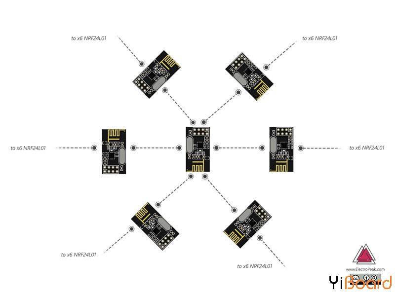
创建网络是NRF模块的优势之一;每个NRF模块可以连接到6个其他模块。
因此,价格合理、易于使用、体积小、网络功能、超远传输距离和合适的数据传输速度使NRF24l01模块成为无线和物联网项目的理想选择。
NRF24L01模块采用SPI协议连接微控制器,有8个引脚:
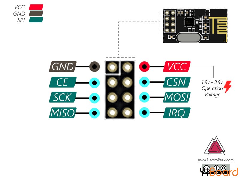
引脚名称 | 功能描述 | GND | 电路接地 | Vcc | 电路供电电压(3.3V) | CE | 芯片使能 | CSN | SPI芯片选择 | SCK | 连接时钟 | MOSI | 从主机Master接收数据 | MISO | 向主机Master发送数据 | IRQ | 中断引脚 |
所需的材料 ● Arduino UNO R3开发板 ● NRF24L01模块 ● Arduino IDE
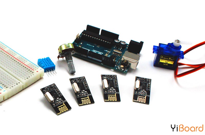
连接两个Arduino开发板以建立无线连接 为了连接两个Arduino开发板,需要两个NRF24L01模块,一个作为主模块,另一个作为从模块。在此示例中,使用主站侧的音量调节旋钮,我们控制从站侧的伺服电机。
电路
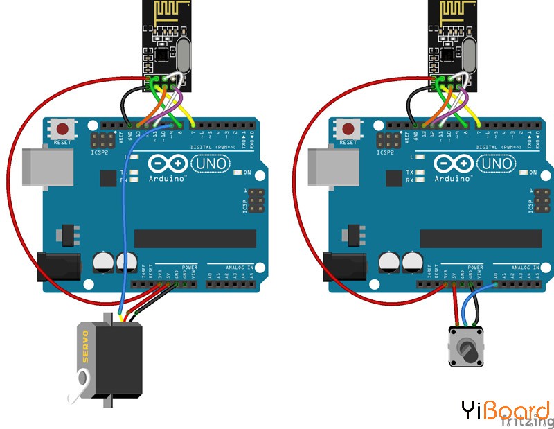
代码 您需要RF24库才能使用NRF24L01模块。从以下链接下载库:Rf24库。 小提示:从模块和主模块需要两个不同的代码才能建立连接。
主模块:上传以下代码到主模块的开发板。 - /*
- NRF24L01 - Controle a servo motor wirelessly
- Master
- modified on 8 Apr 2019
- by Saeed Hosseini @ Electropeak
- https://electropeak.com/learn/
- */
- #include <SPI.h>
- #include <nRF24L01.h>
- #include <RF24.h>
- RF24 radio(7, 8); // CE, CSN
- const byte address[][6] = {"Node1"};
- const int potpin = A0;
- int val = 0;
- void setup() {
- radio.begin();
- radio.openWritingPipe(address);
- radio.setPALevel(RF24_PA_MIN);
- radio.stopListening();
- }
- void loop() {
- val = analogRead(potpin);
- val = map(val, 0, 1023, 0, 179);
-
- radio.write(&val, sizeof(val));
- delay(5);
从模块:上传以下代码到从模块的开发板。 - /*
- NRF24L01 - Controle a servo motor wirelessly
- Master
- modified on 8 Apr 2019
- by Saeed Hosseini @ Electropeak
- https://electropeak.com/learn/
- */
- #include <SPI.h>
- #include <nRF24L01.h>
- #include <RF24.h>
- #include <Servo.h>
- Servo myservo;
- RF24 radio(7, 8); // CE, CSN
- const byte address[][6] = {"Node1"};
- const int servo = 9;
- int val = 0;
- void setup() {
- Serial.begin(9600);
- myservo.attach(servo);
- radio.begin();
- radio.openReadingPipe(0, address);
- radio.setPALevel(RF24_PA_MIN);
- radio.startListening();
- }
- void loop() {
- delay(5);
- radio.startListening();
- if ( radio.available()) {
- while (radio.available()) {
- radio.read(&val, sizeof(val));
- myservo.write(val);
- Serial.print("Servo position = ");
- Serial.println(val);
- }
- }
- }
让我们仔细看看代码: 通过指定CS和CSN引脚为模块创建所需的对象。 - const byte address[][6] = {"addr"};
指定节点的地址。注意,发送方和接收方地址必须相同才能进行通信。 - radio.openWritingPipe(address);
为接收器确定发射器。 - radio.openReadingPipe(0, address);
为发射器确定接收器。 - radio.setPALevel(RF24_PA_MIN);
确定模块的功耗量,该值必须根据发射器和接收器距离确定。 将模块设置为发射器模式。 将模块设置为接收器模式。 - radio.write(&data, sizeof(data));
通过指定数据大小来发送数据。 如果接收器收到数据,则返回值1 - radio.read(&data, sizeof(text));
通过指定数据来接收数据,并将其存储在数据变量中。
创建NRF模块网络 使用NRF24L01模块,您可以创建无线连接并在网络中传输数据。
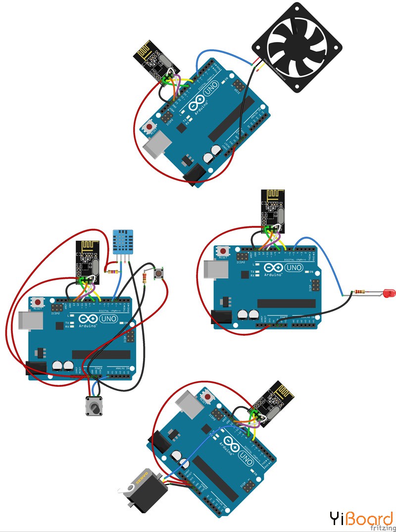
在本示例中,我们要创建一个具有三个从站的网络,并根据从主站发送的温度数据、卷值和密钥状态在从站中执行特定操作。
有两种构建网络的方法,更简单的方法是按照前面的示例进行操作,并且最多有6个单独的地址,通过6个从站向主站发送信息。
在第二种方式中,使用树方法用于组网。因此,主要主服务器仅与其子集相关联,并且每个子集都作为树进行扩展。因此,我们可以构建一个包含最多3125个NRF24L01模块的网络,因此这种方法比第一个更加有效。
电路连接
代码 要使用此方法,您需要RF Network 库。您可以从以下链接下载:RF24Network Library。 主机模块 - /*
- NRF24L01 - Network
- Master
- modified on 8 Apr 2019
- by Saeed Hosseini @ Electropeak
- https://electropeak.com/learn/
- */
- #include <RF24Network.h>
- #include <RF24.h>
- #include <SPI.h>
- #include "dht.h"
- RF24 radio(7, 8); // nRF24L01 (CE,CSN)
- RF24Network network(radio);
- dht DHT;
- const uint16_t this_node = 00;
- const uint16_t node01 = 01;
- const uint16_t node02 = 02;
- const uint16_t node03 = 03;
- const int butpin = 3;
- const int potpin = A0;
- const int dhtpin = 4;
- void setup() {
- SPI.begin();
- radio.begin();
- network.begin(90, this_node); //(channel, node address)
- radio.setDataRate(RF24_2MBPS);
- pinMode(butpin, INPUT);
- Serial.begin(9600);
- }
- void loop() {
- // Send to Node 01
- int potValue = analogRead(potpin);
- int angleValue = map(potValue, 0, 1023, 0, 179);
- RF24NetworkHeader header2(node01);
- bool ok = network.write(header2, &angleValue, sizeof(angleValue));
- // Send to Node 02
- int buttonState = digitalRead(butpin);
- RF24NetworkHeader header3(node02);
- bool ok2 = network.write(header3, &buttonState, sizeof(buttonState));
- // LEDs control at Node 022
- unsigned long pot2Value = analogRead(A1);
- RF24NetworkHeader header4(node03);
- DHT.read11(dhtpin);
- bool ok3 = network.write(header4, &DHT.temperature, sizeof(DHT.temperature));
- }
节点01 - /*
- NRF24L01 - Network
- Node01
- modified on 8 Apr 2019
- by Saeed Hosseini @ Electropeak
- https://electropeak.com/learn/
- */
-
- #include <RF24Network.h>
- #include <RF24.h>
- #include <SPI.h>
- #include <Servo.h>
- RF24 radio(7, 8); // nRF24L01 (CE,CSN)
- Servo myservo;
- RF24Network network(radio); // Include the radio in the network
- const uint16_t this_node = 01; // Address of our node in Octal format ( 04,031, etc)
- const uint16_t master00 = 00; // Address of the other node in Octal format
- const int servopin = 9;
- void setup() {
- SPI.begin();
- radio.begin();
- network.begin(90, this_node); //(channel, node address)
- radio.setDataRate(RF24_2MBPS);
- myservo.attach(servopin);
- }
- void loop() {
- network.update();
- while ( network.available() ) {
- RF24NetworkHeader header;
- int data;
- network.read(header, &data, sizeof(data)); // Read the incoming data
- myservo.write(data);
- }
- delay(5);
- }
节点02 - /*
- NRF24L01 - Network
- Node02
- modified on 8 Apr 2019
- by Saeed Hosseini @ Electropeak
- https://electropeak.com/learn/
- */
- #include <RF24Network.h>
- #include <RF24.h>
- #include <SPI.h>
- RF24 radio(7, 8); // nRF24L01 (CE,CSN)
- RF24Network network(radio); // Include the radio in the network
- const uint16_t this_node = 02; // Address of our node in Octal format ( 04,031, etc)
- const uint16_t master00 = 00; // Address of the other node in Octal format
- const int ledpin = 5;
- void setup() {
- SPI.begin();
- radio.begin();
- network.begin(90, this_node); //(channel, node address)
- radio.setDataRate(RF24_2MBPS);
- pinMode(ledpin,OUTPUT);
- }
- void loop() {
- network.update();
- while ( network.available() ) {
- RF24NetworkHeader header;
- int data;
- network.read(header, &data, sizeof(data)); // Read the incoming data
- digitalWrite(ledpin, !data);
- }
- delay(5);
- }
节点03 - /*
- NRF24L01 - Network
- Node03
- modified on 8 Apr 2019
- by Saeed Hosseini @ Electropeak
- https://electropeak.com/learn/
- */
- #include <RF24Network.h>
- #include <RF24.h>
- #include <SPI.h>
- RF24 radio(7, 8); // nRF24L01 (CE,CSN)
- RF24Network network(radio); // Include the radio in the network
- const uint16_t this_node = 03; // Address of our node in Octal format ( 04,031, etc)
- const uint16_t master00 = 00; // Address of the other node in Octal format
- const int fan = 5; //Red wire to pin 13,Black wire to pin GND
- void setup() {
- SPI.begin();
- radio.begin();
- network.begin(90, this_node); //(channel, node address)
- radio.setDataRate(RF24_2MBPS);
- pinMode(fan, OUTPUT);
- digitalWrite(fan, LOW);
- }
- void loop() {
- network.update();
- while ( network.available() ) {
- RF24NetworkHeader header;
- int data;
- network.read(header, &data, sizeof(data)); // Read the incoming data
- if (data > 70)
- digitalWrite(fan, HIGH);
- else
- digitalWrite(fan, LOW);
- }
- delay(5);
- }
以上就是本篇文章的全部内容。如果有问题,请随时在本帖下面进行回复。 |
 |手机版|YiBoard一板网
( 冀ICP备18020117号 )