风筝
发表于: 2022-7-25 16:33:06 | 显示全部楼层

当您听到拇指操纵杆这个词时,首先想到的是游戏控制器。它们主要用于玩游戏,但是在DIY电子产品中,您可以用它做很多有趣的事情。如控制机器人/漫游车、控制相机的运动;这些只是冰山一角。


硬件概述

这是一个与PS2 (PlayStation 2) 控制器上的模拟操纵杆非常相似的操纵杆。它是一个自定心弹簧加载操纵杆,这意味着当您松开操纵杆时,它会自行居中。它还包含一个舒适的杯型旋钮/盖子,给人一种拇指棒的感觉。

PS2-Joystick-Module-2-Potentiometers-Internal-Structure.jpg


操纵杆的主要作用是将2D(2轴)的运动传达给Arduino开发板。这是通过容纳两个独立的10K电位器(每轴一个)来实现的。这些电位器用作双可调分压器,以控制杆形式提供2轴模拟输入。


电位器是操纵杆侧面的两个蓝色框。如果您在观察每个电位器的中心轴的同时移动操纵杆,您会发现每个电位器仅在一个方向上进行移动。稍后我们将讨论它们实际上是如何工作的。

PS2-Joystick-Module-Push-Button-Switch-Internal-Structure.jpg


该操纵杆还包含一个开关,当您按下盖子时会激活该开关。开关是操纵杆后部的小黑盒子。如果你按下盖子,你会看到一个杠杆按下开关的头部。无论操纵杆处于什么位置,操纵杆都可以工作。


PS2 2轴拇指摇杆模块如何工作?

操纵杆的基本思想是将操纵杆在两个轴上的位置 - X 轴(从左到右)和 Y 轴(上下)转换为Arduino可以处理的电子信息。这可能有点棘手,但要感谢由两个电位器和一个万向节机构组成的操纵杆的设计。


云台机构(Gimbal Mechanism)

2-Axis-Joystick-Working-Gimbal-Mechanism.gif


当您旋转操纵杆时,拇指手柄会移动位于两个可旋转开槽轴(万向节)中的窄杆。其中一个轴允许沿 X 轴(左和右)运动,而另一个轴允许沿 Y 轴运动(上下)。前后倾斜摇杆可左右转动 Y 轴。将其从左向右倾斜可转动 X 轴。当您沿对角线移动操纵杆时,它会转动两个轴。

Potentiometer-Working-In-Joystick-Module.jpg


电位器连接到每个操纵杆轴,将杆的位置解释为模拟读数。移动开槽轴会旋转电位器的接触臂。换句话说,如果您将摇杆一直向前推,它将使电位器接触臂转向轨道的一端,如果将其向后拉,它将使接触臂转向另一端。


从操纵杆读取模拟值

为了读取操纵杆的物理位置,我们需要测量电位器的电阻变化。使用Arduino的ADC模拟引脚可以读取此更改。


由于Arduino开发板的ADC分辨率为10位,因此每个模拟通道上的值可以在0到1023之间变化。因此,如果摇杆在X轴上从一端移动到另一端,X值将发生变化从0到1023,类似的事情发生在沿Y轴移动时。当操纵杆停留在其中心位置时,该值约为512。


下图显示了X和Y方向,还指示了当向各个方向推动操纵杆时输出将如何响应。

PS2-Joystick-Module-Movement-Analog-Values-on-Arduino.jpg


拇指操纵杆模块引脚分配

让我们看一下PS2 2 轴拇指摇杆模块的引脚排列。

Pinout-PS2-Joystick-Module.jpg


GND 接地引脚,连接到Arduino开发板上的GND引脚。

VCC 为模块供电。您可以将其连接到Arduino的5V输出。

VRx 在水平方向(X 坐标)上给出操纵杆的读数,即操纵杆向左和向右推多远。

VRy 给出操纵杆在垂直方向(Y 坐标)的读数,即操纵杆向上和向下推动的距离。

SW 是按钮的输出。它是常开的,这意味着来自SW引脚的数字读数将为高电平。按下按钮时,它将连接到GND,输出低电平。


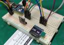
将拇指操纵杆模块连接到Arduino UNO开发板

现在我们已经了解了有关该模块的所有信息,是时候使用它们了!


众所周知,为了确定操纵杆的X和Y坐标,我们需要将操纵杆的两个模拟输出连接到Arduino上的模拟引脚。对于Arduino开发板板,我们将VRx连接到Arduino的模拟引脚A0,将VRy连接到Arduino的模拟引脚A1。


为了读取操纵杆旋钮是否被按下,我们将操纵杆的SW引脚连接到Arduino的数字引脚D8。


除此之外,操纵杆只需要电源。VCC引脚连接到Arduino的5V端子,GND引脚连接到Arduino的GND端子。

Arduino-Wiring-Fritzing-Connections-with-PS2-2-axis-Joystick-Module.jpg


Arduino代码

该程序非常简单。我们将读取两个模拟输入和一个数字输入的测量值。然后我们将在串口监视器上显示结果。

  1. // Arduino pin numbers
  2. const int SW_pin = 8; // digital pin connected to switch output
  3. const int X_pin = 0; // analog pin connected to X output
  4. const int Y_pin = 1; // analog pin connected to Y output

  5. void setup() {
  6.   pinMode(SW_pin, INPUT);
  7.   digitalWrite(SW_pin, HIGH);
  8.   Serial.begin(9600);
  9. }

  10. void loop() {
  11.   Serial.print("Switch:  ");
  12.   Serial.print(digitalRead(SW_pin));
  13.   Serial.print(" | ");
  14.   Serial.print("X-axis: ");
  15.   Serial.print(analogRead(X_pin));
  16.   Serial.print(" | ");
  17.   Serial.print("Y-axis: ");
  18.   Serial.print(analogRead(Y_pin));
  19.   Serial.println(" | ");
  20.   delay(200);
  21. }
复制代码

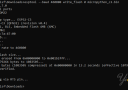
如果一切正常,您应该在串口监视器上看到以下输出。

PS2-Joystick-Module-Arduino-Sketch-Output-on-serial-window.jpg


代码说明

该草图首先在Arduino上初始化操纵杆模块的连接。 SW引脚连接到Arduino的引脚#8,而VRx和VRy引脚连接到模拟引脚#0和#1。

  1. // Arduino pin numbers
  2. const int SW_pin = 8; // digital pin connected to switch output
  3. const int X_pin = 0; // analog pin connected to X output
  4. const int Y_pin = 1; // analog pin connected to Y output
复制代码

setup()函数中:我们将SW引脚初始化为输入并保持为高电平。这是因为只要SW引脚为高电平,我们就知道按钮没有被按下。

  1.   pinMode(SW_pin, INPUT);
  2.   digitalWrite(SW_pin, HIGH);
  3.   Serial.begin(9600);
复制代码

loop() 函数中:我们只使用digitalRead()函数读取SW引脚的值,使用digitalRead() 读取VRx和VRy引脚并显示在串口监视器上。

  1.   Serial.print("Switch:  ");
  2.   Serial.print(digitalRead(SW_pin));
  3.   Serial.print(" | ");
  4.   Serial.print("X-axis: ");
  5.   Serial.print(analogRead(X_pin));
  6.   Serial.print(" | ");
  7.   Serial.print("Y-axis: ");
  8.   Serial.print(analogRead(Y_pin));
  9.   Serial.println(" | ");
  10.   delay(200);
复制代码

跳转到指定楼层
风筝
发表于: 2022-7-25 16:57:34 | 显示全部楼层

在Processing IDE中模拟操纵杆运动

让我们创建一个快速的Arduino项目来演示如何使用简单的2轴操纵杆模块来控制Processing IDE中的动画。首先,我们将编程Arduino,实现在串口上输出x轴、y轴和按钮状态的值。我们将在Processing IDE中接收来自串口的这些值。然后可以使用这些值来设置操纵杆位置的动画。


以下这就是输出的样子。

Arduino-Project-Animating-Joystick-in-Precessing-IDE.gif


当然,这个项目可以扩展到动画角色、监视项目或控制无人驾驶车辆。


Arduino代码

首先,我们需要对Arduino进行编程以在串口上输出x轴、y轴和按钮状态的值。该程序与上面完全相同,只是我们在串口监视器上打印的值是逗号分隔的。为什么用逗号分隔?因为这是将数据从一个应用程序传输到另一个应用程序的流行格式。在Processing IDE中,我们可以通过“逗号”字符分割传入的值并取出我们的数据。


将以下草图上传到您的 Arduino。

  1. int xValue = 0 ; // read value of the X axis        
  2. int yValue = 0 ; // read value of the Y axis        
  3. int bValue = 0 ; // value of the button reading        

  4. void setup()        
  5. {        
  6.         Serial.begin(9600) ; // Open the serial port
  7.         pinMode(8,INPUT) ; // Configure Pin 2 as input
  8.         digitalWrite(8,HIGH);        
  9. }        

  10. void loop()        
  11. {        
  12.         // Read analog port values A0 and A1        
  13.         xValue = analogRead(A0);        
  14.         yValue = analogRead(A1);        

  15.         // Read the logic value on pin 2        
  16.         bValue = digitalRead(8);        

  17.         // We display our data separated by a comma        
  18.         Serial.print(xValue,DEC);
  19.         Serial.print(",");
  20.         Serial.print(yValue,DEC);
  21.         Serial.print(",");
  22.         Serial.print(!bValue);

  23.         // We end with a newline character to facilitate subsequent analysis        
  24.         Serial.print("\n");

  25.         // Small delay before the next measurement        
  26.         delay(10);        
  27. }
复制代码

Processing代码

将程序上传到Arduino后,我们可以在Processing IDE中开始动画操纵杆位置。 保持您的Arduino插入并运行以下处理代码。

  1. import processing.serial.*; //import the Serial library
  2. Serial myPort;

  3. int x; // variable holding the value from A0
  4. int y; // variable holding the value from A1
  5. int b; // variable holding the value from digital pin 2
  6. PFont f; // define the font variable
  7. String portName;
  8. String val;

  9. void setup()
  10. {
  11.   size ( 512 , 512 ) ; // window size
  12.   
  13.   // we are opening the port
  14.    myPort = new Serial(this, Serial.list()[0], 9600);
  15.   myPort.bufferUntil('\n');
  16.   
  17.   // choose the font and size
  18.   f = createFont("Arial", 16, true); // Arial, 16px, anti-aliasing
  19.   textFont ( f, 16 ) ; // size 16px
  20. }

  21. // drawing loop
  22. void draw()
  23. {
  24.   fill(0) ; // set the fill color to black
  25.   clear() ; // clean the screen
  26.   
  27.   fill(255) ; // set the fill color to white
  28.   
  29.   if (b == 1) // check if the button is pressed
  30.   {
  31.     // draw a larger circle with specified coordinates
  32.     ellipse(x/2,y/2, 50, 50);
  33.   }
  34.   else
  35.   {
  36.     // we draw a circle with a certain coordinates
  37.     ellipse(x/2,y/2, 25, 25);
  38.   }
  39.   
  40.   // we display data
  41.   text("AnalogX="+(1023-x)+" AnalogY="+(1023-y),10,20);
  42. }


  43. // data support from the serial port
  44. void serialEvent( Serial myPort)
  45. {
  46.   // read the data until the newline n appears
  47.   val = myPort.readStringUntil('\n');
  48.   
  49.   if (val != null)
  50.   {
  51.         val = trim(val);
  52.         
  53.     // break up the decimal and new line reading
  54.     int[] vals = int(splitTokens(val, ","));
  55.    
  56.     // we assign to variables
  57.     x = vals[0];
  58.     y = vals[1] ;
  59.     b = vals[2];

  60.   }
  61. }
复制代码

代码说明

让我们快速了解一下。首先,我们需要导入串口库以读取来自串口的值。

  1. import processing.serial.*; //import the Serial library
  2. Serial myPort;
复制代码

接下来,声明保存x轴、y轴和按钮状态值的变量。

  1. int x; // variable holding the value from A0
  2. int y; // variable holding the value from A1
  3. int b; // variable holding the value from digital pin 2
  4. PFont f; // define the font variable
  5. String portName;
  6. String val;
复制代码

setup()函数中,我们需要创建一个大小为512×512的窗口来显示动画。接下来,我们通过传递参数 Serial.list()[0] 打开一个可用的串口。如果这对您不起作用,请将其更改为Arduino连接的端口。我们还需要创建一个字体来在窗口上显示我们的值以及动画。

  1.   size ( 512 , 512 ) ; // window size
  2.   
  3.   // we are opening the port
  4.    myPort = new Serial(this, Serial.list()[0], 9600);
  5.   myPort.bufferUntil('\n');
  6.   
  7.   // choose the font and size
  8.   f = createFont("Arial", 16, true); // Arial, 16px, anti-aliasing
  9.   textFont ( f, 16 ) ; // size 16px
复制代码

在draw()函数中,首先窗口的背景是用黑色填充的。然后我们选择一个白色来画一个代表操纵杆位置的小圆圈。现在,根据按钮状态,我们使用 if 语句绘制一个小圆圈或大圆圈。

  1. fill(0) ; // set the fill color to black
  2.   clear() ; // clean the screen
  3.   
  4.   fill(255) ; // set the fill color to white
  5.   
  6.   if (b == 1) // check if the button is pressed
  7.   {
  8.     // draw a larger circle with specified coordinates
  9.     ellipse(x/2,y/2, 50, 50);
  10.   }
  11.   else
  12.   {
  13.     // we draw a circle with a certain coordinates
  14.     ellipse(x/2,y/2, 25, 25);
  15.   }
复制代码

接下来,我们在窗口的左上角打印x轴和y轴值。

  1.   // we display data
  2.   text("AnalogX="+(1023-x)+" AnalogY="+(1023-y),10,20);
复制代码

serialEvent(Serial myPort) 是一个自定义函数,它读取串口上的字符串,直到出现换行符。然后字符串由“逗号”字符分割并分配给相应的变量。

  1. void serialEvent( Serial myPort)
  2. {
  3.   // read the data until the newline n appears
  4.   val = myPort.readStringUntil('\n');
  5.   
  6.   if (val != null)
  7.   {
  8.         val = trim(val);
  9.         
  10.     // break up the decimal and new line reading
  11.     int[] vals = int(splitTokens(val, ","));
  12.    
  13.     // we assign to variables
  14.     x = vals[0];
  15.     y = vals[1] ;
  16.     b = vals[2];

  17.   }
  18. }
复制代码

模拟操纵杆的问题

模拟操纵杆系统存在几个小而重要的问题。

●    首先,粗略的模数转换过程不是很准确,因为系统没有真正的模数转换器。这在一定程度上损害了操纵杆的灵敏度。

●    其次,微控制器必须投入大量的处理能力来定期“轮询”操纵杆系统以确定操纵杆的位置。这会从其他操作中消耗大量资源。

回复

使用道具 举报

您需要登录后才可以回帖 登录 | 立即注册

本版积分规则

主题 700 | 回复: 1479


手机版|

GMT+8, 2024-3-29 03:58 , Processed in 0.093136 second(s), 7 queries , Gzip On, MemCache On. Powered by Discuz! X3.5

YiBoard一板网 © 2015-2022 地址:河北省石家庄市长安区高营大街 ( 冀ICP备18020117号 )

快速回复 返回顶部 返回列表