|
LED闪烁(Blink)
本示例展示了你可以使用Arduino或者Genuino查看物理输出所要做的最简单的事情:闪烁LED。
所需硬件
- Arduino或者Genuino开发板 - LED - 220欧电阻
电路连接方式
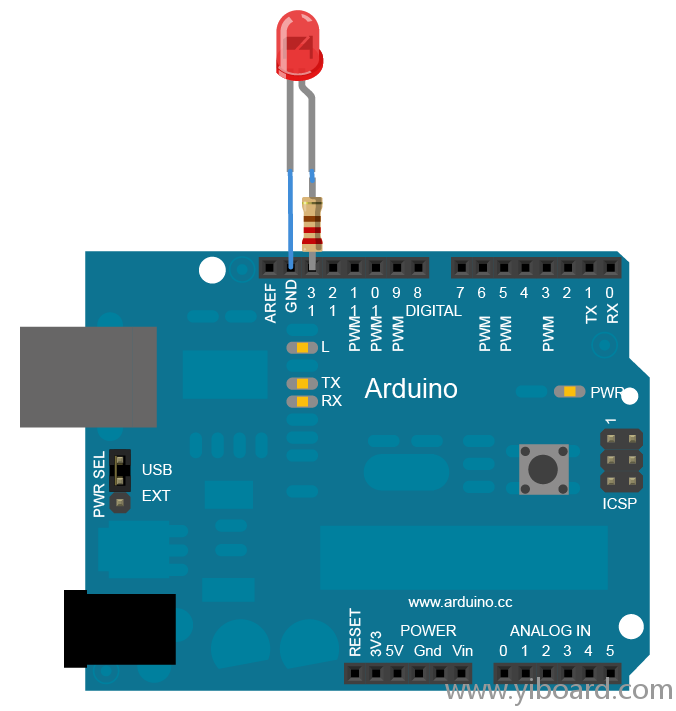
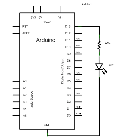
搭建电路时,将电阻的一端连接到Arduino的13引脚。将LED的长腿的一端(正极引脚,称为阳极)连接到电阻的另一端。将LED的短腿(负极引脚,称为阴极)连接到Arduino的GND,如下面的示意图和原理图所示。
大部分的Arduino板已经将板载的LED连接到13引脚。如果没有连接任何其他的硬件并运行本示例,你应该会看到LED闪烁。
与LED串联的的电阻值可以与220欧不同,电阻值大于1K时LED也会点亮。

原理图

代码 当电路搭建后,将Arduino或Genuino板插入到计算机,启动Arduino软件(IDE),并输入以下代码。也可以从菜单File/Examples/01.Basics/Blink加载。你要做的第一件事就是将13引脚初始化为输出引脚,使用以下代码:
在主循环中,使用以下代码点亮LED:
这将向13引脚输出5V电压。在LED的引脚间产生电压差,并将其点亮。然后可以使用以下代码将LED熄灭:
这将使得13引脚回到0V,并熄灭LED。在点亮和熄灭之间,需要足够的时间来让一个人可以看到变化,因此delay()函数可以让开发板空闲1000毫秒,或者是1秒。当使用delay()函数时,在该段时间内没有事情发生。一旦你理解了这个基本的例子,可以参看BlinkWithoutDelay例子来学习如何在延迟时做其他事情。
当你明白了这个例子后,可以参看DigitalReadSerial例子来学习如何读取与主板相连的开关状态。 - /*
- Blink
- Turns on an LED on for one second, then off for one second, repeatedly.
- Most Arduinos have an on-board LED you can control. On the Uno and
- Leonardo, it is attached to digital pin 13. If you're unsure what
- pin the on-board LED is connected to on your Arduino model, check
- the documentation at http://www.arduino.cc
- This example code is in the public domain.
- modified 8 May 2014
- by Scott Fitzgerald
- */
- // the setup function runs once when you press reset or power the board
- void setup() {
- // initialize digital pin 13 as an output.
- pinMode(13, OUTPUT);
- }
- // the loop function runs over and over again forever
- void loop() {
- digitalWrite(13, HIGH); // turn the LED on (HIGH is the voltage level)
- delay(1000); // wait for a second
- digitalWrite(13, LOW); // turn the LED off by making the voltage LOW
- delay(1000); // wait for a second
- }
|  |手机版|YiBoard一板网
( 冀ICP备18020117号 )